MAX7219 – 4 in 1 LED Dot Matrix Display Module Functions
Hello friends! Welcome back to ElectroDuino. This blog is base on MAX7219 – 4 in 1 LED Dot Matrix Display | How MAX7219 – 4 in 1 LED Dot Matrix Display Works. Here we will discuss the introduction 4 in 1 LED Matrix Display module, pin diagram/pinout, module hardware overview, its Specifications, and applications.
Introduction
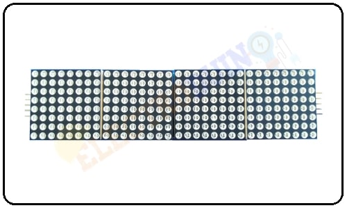
A 4 in 1 dot led matrix display module is a display board arranged in series from four 8 x 8 Dot Matrix which can print characters using LEDs or the group of LEDs. Another most interesting thing about it is the cheap price, easily available in the market, and easy to interface with microcontrollers. this display made of 32 columns and 8 rows of LEDs. So it has total of 32×8 = 256 numbers of LEDs. Each 8×8 LED matrix has a MAX7219 common-cathode display driver IC with serial input and parallel output. So the display module has four MAX7219 display driver IC. Which is make the display easier to control using a microcontroller and microprocessor.
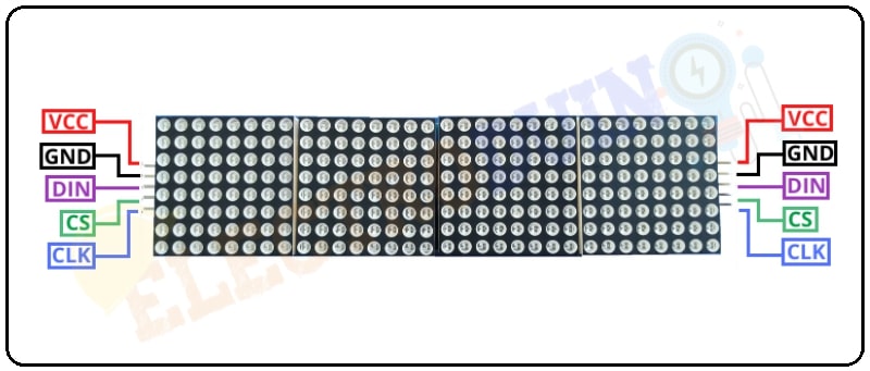
MAX7219 – 4 in 1 LED Dot Matrix Display Module Pin Diagram
| Pin No | Pin Name |
Input Pin Description (Left Side pin) |
Output Pin Description (Right Side pin) |
||||||||||||
| 1 | VCC | Connect to + 5v power supply |
If we want to connect more than one module we just connect the output pins of the previous display board to the input pins of the new module.
|
||||||||||||
| 2 | GND | Connect to the ground of power supply | |||||||||||||
| 3 | DIN | This is a data input pin. Connect to the microcontroller I/O pin to providing data to display. | |||||||||||||
| 4 | CS | This Chip-Select Input. It allows chip activation. | |||||||||||||
| 5 | CLK | This is a Serial-Clock Input pin. Connect to the microcontroller I/O pin to providing clock input to display. |
MAX7219 4 in 1 LED Dot Matrix Display Module Hardware Overview
This Display Module consists of two main components, one is four 8 x 8 LED matrix display and four MAX7219 display driver IC.
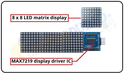
8 x 8 LED Dot Matrix Display
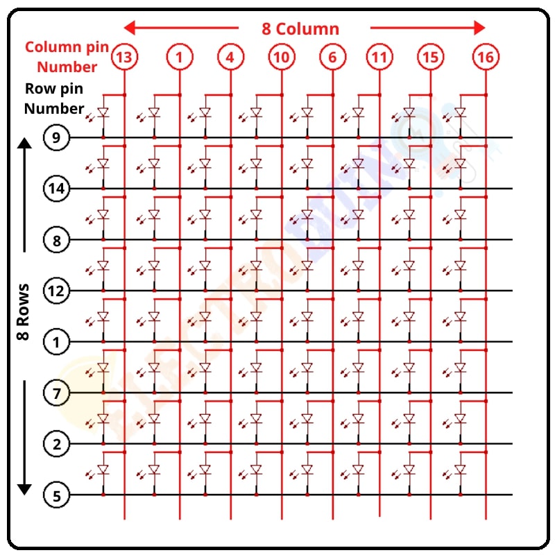
These matrix display modules are made of four 8×8 common cathode matrix. Each LED matrix has 8 rows of LED and 8 columns of LED, so each matrix has a total of 8×8 =64 numbers of LED. This matrix has the LEDs anodes are connected across rows (8 pins) and the LEDs cathodes are connected across columns (8 pins each), it means every display has total of 16 pins to control the LEDs. So, the 4 in 1 dot led matrix display module to consist of 32 columns and 8 rows of LEDs. So it has a total of 32 x 8 = 256 numbers of LED. Which make it bigger and space full to print characters.
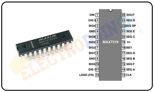
MAX7219 Display Driver IC
When we will remove one matrix display from the 4in1 matrix module board then we will see one chip is soldered on the circuit board of behind the matrix display. This way the 4in1 matrix module board consists of four chips. These chips are known as MAX7219 display driver IC.
The MAX7219 driver IC input interface is a 16-bit serial input shift register. It is a 24-pin IC available in different packages. This IC is basically used to convert serial data to parallel data. The MAX7219 are compact, serial input/output common-cathode display drivers that easy to interface with microcontrollers for control 7-segment numeric LED displays of up to 8 digits, bar-graph displays, or 64 individual LEDs. Included on the MAX7219 chip is a BCD code-B decoder, a multiplex scan circuitry, a segment and digit drivers, and an 8×8 static RAM that stores each digit. One external resistor is needed to set the segment current for all the LEDs. This MAX7219 driver IC can control 64 LEDs using only 3 pins of a microcontroller or microprocessor. So this IC is used to reducing I/O pin usage of microcontroller or microprocessor and you can connect more 8×8 matrix display in series to increase the display size.
Specifications
| Parameter | Value |
| Input Voltage | 3.7 to 5.3 V |
| Input Current | 320 mA |
| Driver Chip | four MAX7219 |
| 8×8 matrix | four 1088AS |
| 8×8 matrix wavelength | 625 ~ 630nm |
| Emitted color | Red |
| PCD Dimensions | 128 x 32 x 1.5cm(LxWxH) |
Applications
- OUTDOOR displays
- POSTER display.
- PIXEL gaming.
- Character design.
- Electronic, DIY projects.
Content Sources: MAX7219 – 8X8 LED Dot Matrix Display Module Functions