Introduction to DS1307 RTC Module
Hello friends! Welcome back to ElectroDuino. This blog is base on Introduction to DS1307 RTC Module. Here we will discuss Introduction to DS1307 RTC Module, module pin diagram, hardware overview, Features, and applications.
Introduction
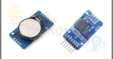
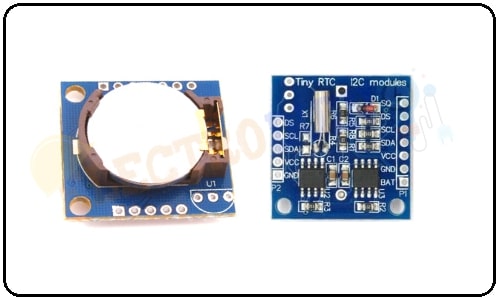
The DS1307 RTC module is a time tracking device that gives the current time and date. The word RTC is meant Real Time Clock. The RTC module made of clock chip DS1307. This module is generally used in computers, laptops, mobiles, embedded system applications devices, etc. to provide time and date. RTC module works on the I2C protocol. The module provides details such as second, minute, hour, day of the week, day of the month, month, and year including correction for leap year. One more interesting thing It can operate either in 12 Hours or in 24 Hours format. It’s can be used in projects like containing data-logging, clock-building, time stamping, timers, and alarms.
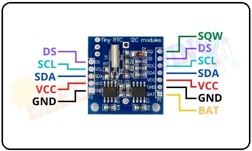
DS1307 RTC Module Pin Diagram
| Pin Name | Description |
| SQW | The SQW pin has a cool feature, it can produce outputs one of four square-wave frequency 1 Hz, 4 kHz, 8 kHz, or 32 kHz and can be possible programmatically. |
| DS | This pin is used to read Output from the DS18B20 temperature sensor if the RTC module has a DS18B20 temperature sensor installed. |
| SCL | This is a clock input I2C serial communication pin. It is used to synchronize data movement on the serial interface. |
| SDA | This pin is used for the data input/output for the I2C serial interface. |
| VCC | It is a positive power input pin of the module in range 3.3V to 5.5V. |
| GND | GND is a negative(ground) power input pin |
| BAT | BAT pin is a backup supply input for any standard 3V lithium cell or other energy sources to maintain accurate timekeeping when the main power to the device is interrupted. |
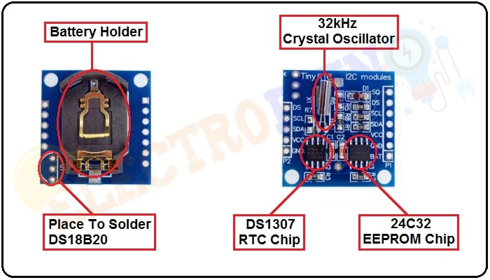
DS1307 RTC Module Hardware Overview
The DS1307 RTC module is consists of mainly 5 key components. These are DS1307 RTC chip, 32kHz crystal oscillator, 24C32 EEPROM chip, battery holder, and soldering place for DS18B20 temperature sensor
DS1307 RTC chip
The DS1307 RTC chip is a low power, full binary-coded decimal (BCD) clock/calendar RTC (Real Time Clock) IC with 56 bytes of SVRAM that communicates through I2C Protocol. The DS1307 is 8 pin IC. The IC is operated on low power consumption when it operated on a battery then it consumes less than 500 nA power. It manages all timekeeping functions.
This IC clock/calendar provides seconds, minutes, hours, day, date, month, and year information. The clock can provide time in the format of 24-hour or 12-hour with AM/PM indicator. The most interesting things are it can automatically adjust the end date of a month, like 31 or 28 days in a month. Also, it can corrections for leap year.
32kHz Crystal Oscillator
This module also consists of a 32kHz crystal oscillator. It is connected between the DS1302 IC pin1 and pin2. crystal oscillator provides frequency to the IC to operate time-keeping functions.
But the external temperature can affect the oscillation frequency of these crystals. This change in the oscillation frequency can be negligible but it surely adds up.
24C32 EEPROM chip
Also, the RTC module comes with a 32 bytes Atmel 24C32 EEPROM chip, which having limited read-write cycles. This EEPROM chip can be used to save settings or clock/calendar. It uses the I2C interface for communication and shares the same I2C bus as DS1307.
Battery Holder
The bottom side of the module has a battery holder for a 20mm 3V lithium coin cell. Any CR2032 battery can fit in the battery holder. The DS1307 incorporates a battery input and maintains accurate timekeeping when the main power to the device is interrupted.
The built-in power-sense circuit continuously monitors the status of the input (VCC) power supply to detect power failures and automatically switches to the backup supply. So, it can continue to maintain the time and date while device power is incorrect.
Soldering Place for DS18B20
One more interesting feature of the module is it has a Soldering place to install a DS18B20 temperature sensor. The module has the 3 holes in the corner left next to the battery holder where we can solder the temperature sensor. if you will install it you can be able to get temperature readings from the DS pin. It can be used in temperature based time drift projects.
Sensor Specifications
| Parameter | Value |
| Range of Operating Voltage | 3.3V – 5V |
| Typical voltage supply | 5V |
| Real Time lock chip | DS1307 I2C |
| EEPROM Chip | AT24C32 32K I2C EEPROM memory |
| Battery type | LIR2032 rechargeable lithium battery |
| Power consumption | It operated on a battery then it consumes less than 500 nA power. |
| Clock Provide | Hour, Minutes, Seconds, AM/PM. |
| Calendar provides | Day, Date, Month, Year. |
| PCB Size | 27mm * 28mm * 8.4mm (L*W*H) |
Application
- To design real time clock.
- DIY projects.
- Robotics projects.
- Arduino projects.
- Raspberry-Pi projects.
- Electrical/Electronic projects.