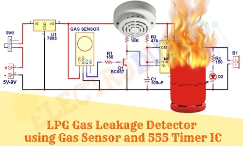
LPG Gas Leakage Detector Project using Gas Sensor
Hello friends! Welcome back to ElectroDuino. This blog is based on LPG Gas Leakage Detector Project using Gas Sensor and 555 Timer IC. Here we will discuss Introduction to LPG Gas Leakage Detector Project, Project Concept, Block Diagram, Components Required, Circuit Diagram, and Working Principle.
Introduction
LPG is an essential fuel in our daily life. In these modern days, LPG gas is used in every kitchen for cooking, as well as it’s used in different industries and factories. While it is a very useful burning fuel, but it is a highly explosive gas. Normally LPG gas is available in a cylinder. The LPG gas is heavier than air, when it leaks from a cylinder it flows along the floor and it can happen an explosion and cause fire accidents. So, in this project, we will build the LPG Gas Leakage Detector system, that can detect LPG gas and alert us through Sounds and Light indicator. It can save us from a big explosion or fire accident.
Project Concept
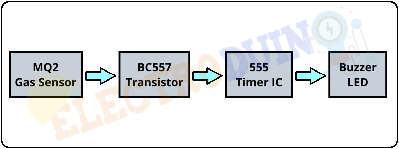
The LPG Gas Leakage Detector Project is based on a very simple concept and it very easy to build. When this system detects LPG gas, it alerts us by turn on the LED and Buzzer. The key components are the MQ2 gas sensor module, BC557 Transistor, 555 Timer IC, LED, and Buzzer. The MQ6 is a gas sensor module, which can scene LPG, Alcohol, Propane, Hydrogen, CO, and even methane. Here we will use it to detect LPG. The BC557 transistor work as a switching device, it is activated by the sensor output. Here it is used to drive the 555 Timer IC. The 555 Timer IC is the main Chip, it generates output to control LED and Buzzer. The LED and Buzzer are work as an indicator.
Block Diagram of LPG Gas Leakage Detector Project
Components Required
| Components Name | Quantity |
| NE555 Timer IC (U2) | 1 |
| 7805 Voltage Regulator (U1) | |
| BC557 Transistor (Q1) | 1 |
| MQ2 Gas Sensor Module | 1 |
| 150 ohm Resistor (R1, R4) | 2 |
| 10K ohm Resistor (R2) | 1 |
| 47K ohm Resistor (R3) | 1 |
| 100 uF Capacitor (C1) | 1 |
| 0.01uF Capacitor (C2) | 1 |
| Red LED (D1) | 1 |
| Buzzer (B1) | 1 |
| Slide Switch (SW1) | 1 |
| 5V to 9V Power Supply | 1 |
| PCB board | 1 |
| Connecting Wire | As required in the circuit diagram |
Tools Required
| Tools Name | Quantity |
| Soldering Iron | 1 |
| Soldering wire | 1 |
| Soldering flux | 1 |
| Soldering stand | 1 |
| Multimeter | 1 |
| Desoldering pump | 1 |
| Wirecutter | 1 |
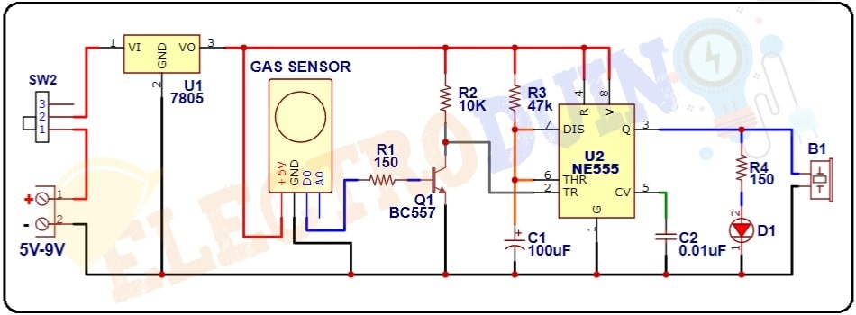
Circuit Diagram of LPG Gas Leakage Detector Project
Working Principle LPG Gas Leakage Detector Project
When we will turn on the circuit power supply between 5v to 12v, then the 7805 voltage regulator IC converts the input voltage into 5v output. Because MQ2 Gas Sensor Module operates on 5v input voltage. The MQ2 gas sensor module can sense LPG. Here the 555 timer IC configured in monostable mode, so when it gets a LOW (Ground) trigger pulse at its trigger pin, then the IC OUTPUT becomes High.
After turn on the power supply MQ2 gas sensor start sensing LPG gas is present in the air or not. If LPG gas leaks from a cylinder then the MQ2 gas sensor detects it and provides LOW (Ground/0v) output voltage from the “D0” pin. This output voltage goes to the Base terminal of the BC557 Transistor and the transistor becomes active. Now it starts conducting and the 555 timer ic trigger pin (IC pin 2) connects to the ground. Then the IC produces High out from Pin 3. This output voltage goes to the LED and Buzzer. Then the LED starts glowing and the buzzer generates Sound.