LED Brightness Control Using Arduino and Potentiometer
Hello friends! Welcome back to ElectroDuino. This is the Arduino Tutorial #7 – LED Brightness Control Using Potentiometer. After understanding Arduino AnalogRead using Potentiometer in the Arduino Tutorial #6. In this blog, we going to describe the Project concept, What is the map in Arduino, LED Brightness Control Using the Potentiometer circuit diagram, and Arduino Code/sketch.
Project Concept of LED Brightness Control
In this project, we will control LED brightness using the Potentiometer. This project concept is based on the “Arduino AnalogRead using the Potentiometer” and “Digital pin PWM output | Arduino LED Fading“, which is explained in the previous tutorials. Here we will read analog output from the potentiometer using Arduino and control the LED using PWM output. Also, use the map( ) function in the Arduino code.
Components Required
| Components Name | Quantity |
| Arduino Uno R3 | 1 |
| USB cable for Arduino Uno | 1 |
| 10k Potentiometer | 1 |
| LED | 1 |
| 220Ω Resistor | 1 |
| Connecting wire | As per required in the circuit diagram |
Analog input read from the potentiometer
First of all, we need to connect the Potentiometer terminal 1 is connected to +5v Vcc, and terminal 3 is connected to the ground. Now we can read the output from terminal 2 of the potentiometer, and we need to connect this terminal to an analog pin of the Arduino board. Arduino analog pin has 10-bit Analog to Digital Converter(ADC), which converts the potentiometer output voltage into integer value between the range of 0 to 1023 volts (2^10 = 1024) as input. Where the value “0” represents “0 volts” and the value “1023” represents “5 volts”. When we will Rotate the potentiometer knob, then the output voltage is changed and the Arduino reads this change of output voltage as the input voltage.

Digital output on the LED
Another side, the positive terminal of the LED is connected to the PWM(Pulse Width Modulation) pin. This pin provides analog results with digital means at the range of 0 to 255. Where the value “0” represents “0 volts” and 255 represents “5 volts”. The LED brightness changes from Low to High according to the change of the PWM output value from 0 to 255.

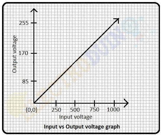
In this project, we will change the LED brightness by rotating the potentiometer knob. We will increase and decrease the LED brightness value between 0 to 255 according to the changing potentiometer output value between 0 to 1023. When the potentiometer output value is 0 then the LED input value is 0 and the LED brightness is LOW (off). When the potentiometer output value is 1023 then the LED input value is 255 and the LED brightness is High. This graph represents how output voltage is increased or decreased according to the potentiometer output voltage. To work this operation we need to use a function called map() in Arduino Code.
What is the map( ) Function in Arduino Code
Re-maps a number from one range to another. That is, a value of fromLow would get mapped to toLow, a value of fromHigh to toHigh, values in-between to values in-between, etc.
Note that the “lower bounds” of either range may be larger or smaller than the “upper bounds” so the map() function may be used to reverse a range of numbers, for example
y = map(x, 1, 50, 50, 1);
The function also handles negative numbers well, so that this example
y = map(x, 1, 50, 50, -100);
is also valid and works well.
Syntax
map(value, fromLow, fromHigh, toLow, toHigh)
Parameters
value: the number to map.fromLow: This is the lower bound of the input voltage range.fromHigh: It is the upper bound of the input voltage range.toLow: This is the lower bound of the output voltage range.toHigh: It is the upper bound of the output voltage range.
LED Brightness Control Using Potentiometer Circuit diagram / Schematic

Circuit Wiring
| Components Pins | Arduino Pins |
| Potentiometer terminal 1 | 5v pin |
| Potentiometer terminal 2 | Arduino analog pin “A0” |
| Potentiometer terminal 3 | GND pin |
| LED positive (+) terminal | Connected to Arduino Digital pin “D5” through a 220-ohm resistor. |
| LED negative (-) terminal | Connected to GND pin |
LED Brightness Control Using Potentiometer Code/sketch
/*
Arduino Tutorial #7 - LED Brightness Control Using Potentiometer
http://www.electroduino.com
*/

const int analogInPin = A0;
const int analogOutPin = 6;

int sensorValue = 0;
int outputValue = 0;

void setup()
{
Serial.begin(9600);
}

void loop() {

sensorValue = analogRead(analogInPin);

outputValue = map(sensorValue, 0, 1023, 0, 255);


analogWrite(analogOutPin, outputValue);

Serial.print("sensor = ");
Serial.print(sensorValue);
Serial.print("\t output = ");
Serial.println(outputValue);

delay(2);
}
Code Analysis
| Code Line | Description |
const int analogInPin = A0; |
This line is declared your potentiometer output pin connected to Arduino analog pin “A0” and named as analogInPin. |
const int analogOutPin = 6; |
This line is declared your LED positive pin connected to Arduino digital pin 6 and named as analogOutPin. |
int sensorValue = 0;int outputValue = 0; |
Define two variables sensorValue and outputValue. At the starting of the code, we set these values at 0. |
Serial.begin(9600); |
This function is used to begin serial communication, at 9600 bits of data per second, between your Arduino board and your computer. |
sensorValue = analogRead(analogInPin); |
This line is the main function of the code. It is used to read output value from the potentiometer and That output value is stored in the “sensorValue” variable in the range between 0 to 1023. |
outputValue = map(sensorValue, 0, 1023, 0, 255); |
output Value is assigned to equal the scaled value from the potentiometer output. The map() function accepts five arguments: The value to be mapped (sensorValue), the low range and high values of the input data (Potentiometer output), and the low and high values for that data to be remapped to the output (LED input). Here, the potentiometer output is mapped down from the range of 0 to 1023 to 0 to 255. |
analogWrite(analogOutPin, outputValue); |
analogWrite is used to provide output to the LED. |
Serial.print("sensor = ");Serial.print(sensorValue);Serial.print("\t output = ");Serial.println(outputValue); |
Finally, you need to print the sensor (pot) value and output value on your serial monitor window using this command. |
delay(2); |
Wait for 2 milliseconds to see the result clearly. |
Output Result
As a result, you can see LED brightness change according to the rotation of the potentiometer knob.
The map( ) Function data Content Credit: map() – Arduino Reference