
Light Detector Sensor using Arduino and LDR.
Hello friends! Welcome back to ElectroDuino. This is the Arduino Tutorial #9 – Arduino Light Detector Sensor using LDR. After understanding Arduino Push Button DigitalRead in Arduino Tutorial #8. In this blog, we going to describe What is Light Detector Sensor, What is an LDR, the Project Working Principle, the Arduino Light Detector Sensor Code/sketch, and the circuit diagram.
Project concept
In this tutorial, we will make Light Detector Sensor using LDR which can detect dark and light then indicate the output result by a LED. When LDR senses dark then the system turns ON the LED and when LDR senses light then the system turns OFF the LED. This project is based on a very helpful concept, whenever a room gets dark, the light automatically turns ON and eliminates the darkness.
Light Detector Sensor
A Light Detector or a Light Sensor is a circuit that can detect the light intensity when light falls on it. It is a photoelectric device that can convert detected light energy (photons) to electrical energy (electrons). The main component of the Light Detector Sensor circuit is light detecting elements. Different types of light detecting elements are available in the market these are Photoresistors, photodiodes, phototransistors, etc. Different types of Light Detectors Sensors can detect different types of light like visible light, ultraviolet light, infrared light, etc. In this project, we are using an LDR or Light Dependent Resistor to detect visible light.
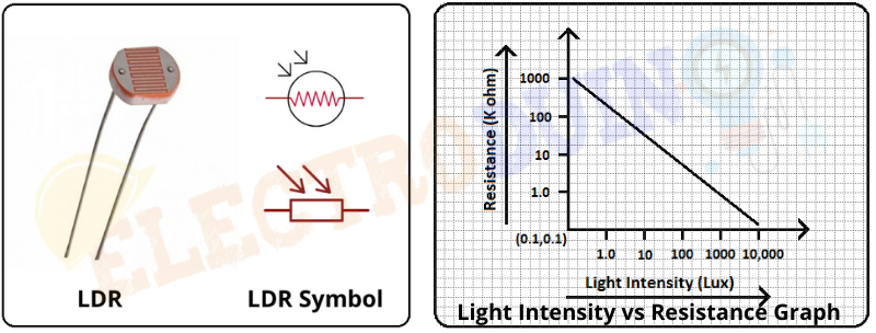
What is an LDR or Light Dependent Resistor?
LDR or Light Dependent Resistor is a variable resistor. It is also known as a photoresistor. These LDR, Light Dependent Resistor, or Photoresistor works on the principle of “Photo Conductivity”. The LDR resistance change depends on the light intensity that falls on the LDR surface. When light falls on the surface of the LDR then the resistance of the LDR decreases and increases the conductance of the element. When no light falls on the surface of the LDR then the resistance of the LDR is high and decreases the conductance of the element.
Analog input read from LDR
When we connect the LDR circuit to the Arduino, LDR gives output an analog voltage to Arduino in the range of 0 to 5v. Arduino reads the output voltage using an analog pin. Analog pins have ADC (analog-to-digital converter). Which converts the analog voltage into a digital value in the range of 0 -1023. This value will be dependent on the change in light intensity which falls on the LDR surface. When it gets maximum intensity light this value is High and the value is Low for minimum light intensity.
Digital output on the LED
We will control a LED using this value. The led is connected to the Arduino digital pin. When Arduino gets the maximum value from LDR so it means dark and it will automatically turn ON the LED. When Arduino gets the minimum value from LDR so it means Light and it will automatically turn OFF the LED.
Components Required
| Components Name | Quantity |
| Arduino Uno | 1 |
| USB cable for Arduino Uno | 1 |
| LDR or Light Dependent Resistor | 1 |
| LED | 1 |
| 10k Resistor | 1 |
| 200-ohm Resistor | 1 |
| Connecting wire | As per required in the circuit diagram |
Arduino Light Detector Sensor using LDR Circuit diagram / Schematic
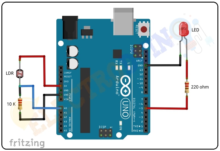
Circuit Wiring
| Components Pins | Arduino Pins |
| LDR terminal 1 | +5 v Vcc |
| LDR terminal 2 | connected to Arduino GND pin through a 10K ohm resistor. |
| The output pin is LDR terminal 2 and the resistor connection point | analog pin “A0” |
| LED positive (+) terminal | connected to Arduino digital pin “D5” through a 220 ohm resistor |
| LED negative (-) terminal | Arduino GND pin |
Arduino code for Light Detector Sensor using LDR and LED
/*
Arduino Tutorial #9 – Arduino Light Detector Sensor using LDR
http://www.electroduino.com
*/

const int ldrPin = A0;
const int ledPin = 5;

void setup()
{
  pinMode(ldrPin, INPUT);
  pinMode(ledPin, OUTPUT);
  Serial.begin(9600);
}

void loop()
{
  int ldrStatus = analogRead(ldrPin);

 if (ldrStatus >= 800)
 {
  digitalWrite(ledPin, HIGH);
  Serial.print("Its DARK, Turn on the LED : ");
  Serial.println(ldrStatus);
 }

 else
 {
  digitalWrite(ledPin, LOW);
  Serial.print("Its LIGHT, Turn off the LED : ");
  Serial.println(ldrStatus);
 }
}
Code Analysis
Here we will describe the code line by line for your better understanding.
|
Code Line |
Description |
|
|
it is declared your LDR output pin is connected to Arduino analog pin “A0” and named as |
|
|
it is declared your LED pin is connected to Arduino digital pin “D5” and named as ledPin. |
|
|
initialize Arduino analog pin “A0”, as an INPUT. That will read the output from your LDR, |
|
|
initialize Arduino digital pin “D5”, as an OUTPUT. That will provide input voltage to the LED. |
|
|
This function starts serial communication, at 9600 bits of data per second, between your board and your computer with the line. |
|
|
The function |
|
|
If Arduino reads the value greater than or equal to “800” from the LDR then Arduino provides digital value to turn ON the LED. You can print the LDR output value and a message “It’s DARK, Turn on the LED: ” on your serial monitor window using this command. |
|
|
When the Arduino reads a value less than “800” from the LDR then Arduino does not provide digital value to the LED and the LED is turned OFF. You can print the LDR output value and a message “It LIGHT, Turn off the LED: ” on your serial monitor window using this command. |
Output:
When LDR senses dark then the system turns ON the LED and when LDR senses light than the system turns OFF the LED.


This really answered my problem, thanks!