Automatic Street Light Project using LDR and OP-Amp IC
Hello friends! Welcome back to ElectroDuino. This blog is based on the Automatic Street Light Project using LDR and lm358 OP-Amp IC. Here we will discuss Introduction to Automatic Street Light Project, Project Concept, Block Diagram, components required, circuit diagram, working principle.
Introduction
We all have seen street lights on different streets, which are provide light in the night and they are off during the daytime. Normally these street lights are controlled manually, where someone turns on these lights at the night and turn off it in the daytime. But many times they forget to turn off it, which is wasted lots of electricity.
For this reason, in this project, we will design and make a simple circuit that can solve this problem. This is the Automatic Street Light Project, this can turning ON and OFF the street lights automatically without human interference. it automatically turns ON the street light when the surrounding is dark (Night) and it automatically turns OFF the street light when it receives light from the surroundings (Daylight). It can save lots of electricity and decrease human effort.
Project Concept
This is a very simple and low-cost project. Few components are used to build this project. The key components of the Automatic Street Light Project are LDR, LM358 Op-Amp IC, BC547 transistor, and Relay. The LDR is used to detect the Dark and Light of the surrounding. The LM358 Op-Amp IC compares the LDR output in Dark and Light conditions and produces an output voltage. Here the BC547 transistor works as a switch, which is controlled by the output of LM358 Op-Amp IC. This transistor is used to control the Relay. The relay is an electronic switch that can control AC/DC devices. Here the relay controls the AC Street light.
Automatic Street Light Project Block Diagram

Components Required
| Components Name | Quantity |
| LM358 comparator IC | 1 |
| BC547 Transistor (T1) | 1 |
| LDR or Light Dependent Resistor (R2) | 1 |
| 10K Potentiometer (RV1) | 1 |
| 10k ohm Resistor (R1) | 1 |
| 1K ohm Resistor (R3, R4) | 2 |
| 10uf Electrolytic Capacitor (C1) | 1 |
| 1N4007 Diode (D2) | 1 |
| Green LED (D1) | 1 |
| Slide Switch (SW1) | 1 |
| Terminal Block for power input | 1 |
| 9v Power supply | 1 |
| Connecting Wires | As required in the circuit diagram |
Tools Required
| Tools Name | Quantity |
| Soldering Iron | 1 |
| Soldering wire | 1 |
| Soldering flux | 1 |
| Soldering stand | 1 |
| Multimeter | 1 |
| Desoldering pump | 1 |
| Wirecutter | 1 |
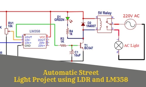
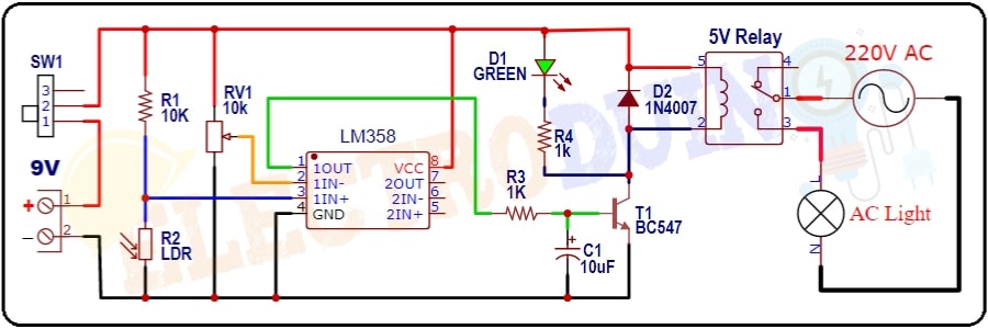
Automatic Street Light Project Circuit Diagram
Circuit Wiring
The LM358 IC Vcc Pin (Pin8) is connected to the positive terminal of the power supply and the ground Pin (Pin4) is connected to the negative terminal of the power supply. The LM358 IC Comparator-1 inverting terminal (IC Pin 2) is connected to a 10 K potentiometer and the node point of 10K ohm resistor (R1) and LDR (R2) is connected at its non-inverting terminal (IC Pin 3). LM358 IC’s output (IC Pin 1) is connected to the base terminal of the BC547 transistor (T1) through a 1K ohm resistor (R4). The transistor collector terminal is connected to the Ground of the 9v power supply and the Emitter terminal is connected to the junction point of the 1k resistor (R4), 1N4007 Diode (D2) Anode(+) terminal, and Relay pin2.
Working Principle of Automatic Street Light Project
The LM358 IC is comparing voltage coming from 10 K Potentiometer (RV1) and LDR (R2). The potentiometer is used to set a reference voltage at the inverting terminal (IC Pin 2) of the comparator-1, it is used to adjust the LDR sensitivity.
Daylight Condition
In the daytime, a huge amount of sunlight is present in the surrounding. So, sunlight directly falls on the LDR surface. This time LDR gives Low output voltage to the non-inverting terminal (IC Pin 3) of the LM358 Op-Amp IC. Then LM358 IC compares this voltage with the reference voltage.
In this condition, the input voltage at the non-inverting terminal (IC Pin 3) is less than the inverting terminal (IC Pin 2) of the IC. So the IC output (Pin1) is Low, So, IC does not provide enough voltage at the base terminal of the transistor. For this reason, the transistor is in off condition, so the Relay is also off. It means Street Light is OFF.
Night (Dark) Condition
In the night time, light does not fall on the LDR surface. This time LDR gives High output voltage to the non-inverting terminal (IC Pin 3) of the LM358 Op-Amp IC. Then LM358 IC again compares this voltage with the reference voltage.
In this condition, the input voltage at the non-inverting terminal (IC Pin 3) of the comparator-1 is greater than the inverting terminal (IC Pin 2) of the comparator-1. So the comparator-1 output is High. Then the transistor will turn on. So the Relay gets input voltage and now it is activated. It means Street Light is ON.