
Interfacing PIR Sensor with Arduino | Motion Detector using PIR Sensor
Hello friends! Welcome back to ElectroDuino. This blog is based on Interfacing PIR Sensor with Arduino | motion Detector using PIR Sensor. In the previous blog post, we were discussing “HC-SR501 (Passive Infrared) PIR Sensor | How it’s Works “. Here we will discuss how to use the PIR sensor module with Arduino, Circuit diagram, Digital data read Arduino Code, motion Detector using PIR Sensor, Circuit diagram, and Arduino Code.
Introduction
Interfacing PIR Sensor with Arduino is a first step to understanding how to use a PIR sensor in different projects. At first, we will learn how to connect a PIR sensor module with Arduino and write a simple Arduino code to read digital data from the sensor. Then we will make a simple project, where the PIR sensor detects motion and indicated by an LED and a buzzer. This simple project helps us to learn how to use this sensor in different projects.
Components Required
| Components Name | Quantity |
| Arduino UNO (you can use other types of Arduino like Arduino Nano, MEGA, pro mini, etc) | 1 |
| Arduino USB Cable (USB A to B) |
1 |
| HC-SR501 PIR Sensor Module | 1 |
| LED | 1 |
| Buzzer | 1 |
| 150 ohm Resistor | 1 |
| Connecting wires | As required in the circuit diagram |
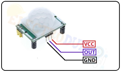
PIR Sensor Module Pin Diagram
PIR sensor module has 3 terminals these are VCC pin, OUT pin, and GND pin.
| For More Details: HC-SR501 (Passive Infrared) PIR Sensor | How it’s Works |
How to use HC-SR501 PIR Sensor Module with Arduino
Using a PIR sensor with Arduino is really simple. First of all, we will connect the sensor VCC pin to the Arduino +5v pin and connect the ground pin to Arduino GND (ground) Pin. Now the sensor is activated and ready for motion detection. After activated the sensor, we need to read the output data from the sensor output pin. HC-SR501 PIR Sensor is a digital output sensor. So we need to connect the sensor Out pin to any one of the digital pins of the Arduino. Here we will connect the sensor Out pin to the digital pin “D4” of the Arduino.
PIR Motion Sensor Arduino Circuit Diagram
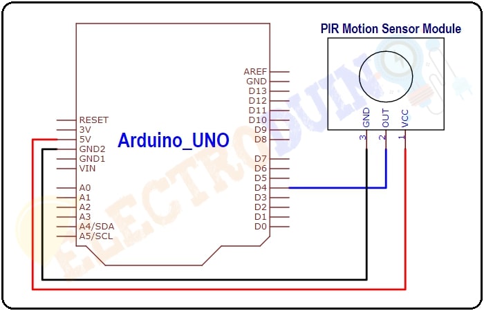
Circuit Wiring
| PIR Sensor Pin | Arduino Pin |
| Vcc Pin | + 5v Pin |
| GND Pin | GND (ground) pin |
| OUT Pin | Digital pin “D4” |
Read Digital Data from PIR Sensor using Arduino Code
After connecting the sensor to an Arduino, now we need to write a few lines of code in Arduino IDE Software. We will use the “digitalRead()” function in the Arduino program to read the sensor output. Also, we will print the sensor output data on the Serial monitor of the Arduino IDE.
/* PIR Sensor Interfacing with Arduino
by sourav
www.electroduino.com */

// Declare your PIR sensor out pin connected Arduino pin “D5”
int PIRSensor = 5;

void setup()
 {
 //Initialize Sensor (pin5) as an INPUT.
  pinMode (PIRSensor, INPUT);
 //Define baud rate for serial communication
  Serial.begin (9600);
 }

void loop()
 {
 // Read output value from sensor
  int PIRdata = digitalRead (PIRSensor);
 //Print the sensor value on your serial monitor window
  Serial.print("Sensor value:");
  Serial.print(PIRdata);
 }
Sensor Output on Serial monitor
When the sensor detects motion then the output goes HIGH(1) and the output goes LOW (0) for no motion detected.
Motion Detector using PIR Sensor
In this part, we will show you how to use PIR as a motion project. Here the PIR sensor used for motion detection, and a LED and a Buzzer are used for motion indicators. This system is controlled by Arduino.
Motion Detector Circuit Diagram using PIR Sensor Module and Arduino
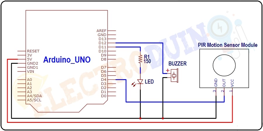
Circuit Wiring
| Components Pin | Arduino Pin |
| PIR sensor Vcc Pin | + 5v Pin |
| PIR sensor GND Pin, LED negative terminal, and Buzzer negative terminal | GND (ground) pin |
| PIR sensor OUT Pin | Digital pin “D4” |
| LED positive terminal | Digital pin “D11” through the 150 ohm resistor. |
| Buzzer Positive terminal | Digital pin “D12” |
How the Motion Detector Circuit works
When the sensor detects motion, then output goes HIGH (1) and Arduino reads this output, Then Arduino sends a command to the LED and Buzzer. Then the LED starts glowing and Buzzer generates sound for 5 seconds.
When the sensor does not detect motion then output goes LOW (0) and Arduino reads this output. Then Arduino sends a command to turn off LED and Buzzer.
Arduino Code for PIR Motion Detector Circuit
/* PIR Sensor Interfacing with Arduino
www.electroduino.com */

// Declare your PIR sensor out pin connected Arduino pin “D5”
int PIRSensor = 4;
// Declare your LED pin connected Arduino pin “D11”
int LEDpin = 11;
// Declare your Buzzer pin connected Arduino pin “D12”
int Buzzerpin = 12;

void setup()
{
pinMode (PIRSensor, INPUT);  //Initialize Sensor (pin5) as an INPUT.
pinMode (LEDpin, OUTPUT);    //Initialize LED (pin11) as an INPUT.
pinMode (Buzzerpin, OUTPUT); //Initialize Buzzzer (pin12) as an INPUT.

Serial.begin (9600); //Define baud rate for serial communication
}

void loop()
{
 // Read output value from sensor
  int PIRdata = digitalRead (PIRSensor);
 //Print the sensor value on your serial monitor window
  Serial.print("Sensor value:");
  Serial.print(PIRdata);

 if (PIRdata == 1)
 {
  //Turn ON LED and Buzzer
  digitalWrite(LEDpin, HIGH);
  digitalWrite(Buzzerpin, HIGH);
  delay(5000); // Delay for 5 seconds
 }

 else
 {
  //Turn OFF LED and Buzzer
  digitalWrite(LEDpin, LOW);
  digitalWrite(Buzzerpin, HIGH);
 }
}


