Full Wave Rectifier – Circuit Diagram and Working Principle
Hello friends! Welcome back to ElectroDuino. This blog is based on Full Wave Rectifier. Here we will discuss what is Full Wave Rectifier, Working Principle, Circuit Diagram, Waveforms, Formula, Advantages, and Disadvantage.
What is a Rectifier?
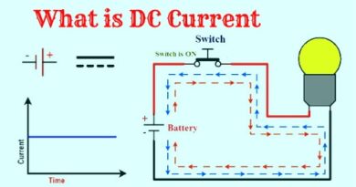
The Rectifier is a simple electronic circuit construct by a single diode or multiple pn junction diodes that converts alternating current (AC) into direct current (DC). The process of convert alternating current (AC) to direct current (DC) is called Rectification.

The rectifiers are mainly classified into two categories, these are Half Wave Rectifier and Full Wave Rectifier. Here we mainly discuss the Full Wave Rectifier.
What is a Full Wave Rectifier
A full-wave rectifier is a form of rectifier that allows both the positive half cycle and negative half cycle of input alternating current (AC) signal to passing, for transform the AC voltage into pulsating DC voltage.

The half-wave rectifier circuit either allows the positive half cycle or negative half cycle of input AC signal to pass through and blocked the remaining half cycle. Therefore a significant amount of power is wasted and the output is not a smooth and steady DC voltage (Current), so, we can’t use it for all dc appliances. But in the full-wave rectifier allows both half-cycles (positive and negative half cycle) to pass through it. That’s why it produces higher DC output voltage and the output is steady DC voltage (Current). For this reason, full-wave rectifiers are preferred over half-wave rectifiers in DC appliances.
We can further classify full-wave rectifiers into two types:
- Center-tapped Full Wave Rectifier
- Full Wave Bridge Rectifier
Here we mainly discuss the center-tapped Full Wave Rectifier.
|
Also See |
What is center Tapped Full Wave Rectifier
A rectifier circuit that uses a center-tapped transformer and 2 diodes to convert the complete Alternating current (AC) signal into a Direct current (DC) signal, known as a center-tapped full-wave rectifier.
Construction and Circuit Diagram of center-tapped Full Wave Rectifier
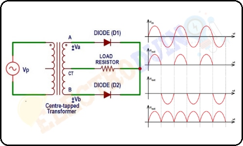
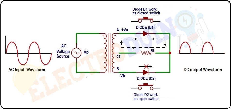
A complete Center-tapped Full Wave Rectifier circuit consists of four main parts, these are a Center-tapped transformer, two diodes, a resistive load, and also need an AC voltage source. The following figure is the circuit diagram of the Center-tapped Full Wave Rectifier.

The primary winding of the Center-tapped transformer is connected with an AC voltage source. The terminal-A of the secondary winding is connected to the Anode or positive (+) terminal of the diode D1 and the terminal-B of the secondary winding is connected to the Anode or positive (+) terminal of the diode D2. The Cathode or negative (-) terminal of both diodes (D1 and D2) are connected to one side of the load resistor(RL). Another side of the load resistor(RL) is connected to the Common Terminal (CT) of the secondary winding.
Center Tapped Transformer
When an additional wire is connected to the exact middle of the secondary winding of a transformer, it is known as a center-tapped transformer.
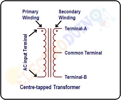
The center-tapped transformer produces a two-phase, 3-wire supply. The secondary winding of the center-tapped transformer divided into two parts, the upper part (UP) and the lower part (LP). So, the center-tapped transformer divides the input AC current signal (VP) into two equal but opposite secondary voltages (Va and Vb). The secondary winding of the center-tapped transformer has three terminals. Terminal-A is connected to the upper part and terminal-B is connected to the lower part of the Secondary winding. The additional wire is connected in the exact middle point of the secondary winding (secondary coil), this point is known as the tapping point. This wire or tapping point is exactly at zero volts of the AC signal and it providing a common connection (Common Terminal (CT)) for two terminals (A and B).
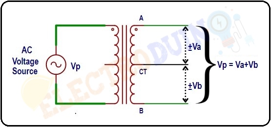
The voltages Va and Vb are equal in magnitude but opposite in direction. If Terminal-A of the secondary winding produces a positive voltage (+Va), then the Terminal-B of the secondary winding will produce a negative voltage (-Vb). When we combine these two voltages (+Va and -Vb) at output load, we get a complete AC signal.
I.e. Vp = Va + Vb
That why they are 180 electrical degrees out-of-phase with each other.
Working/Operation of center-tapped Full Wave Rectifier (Theory)
When we apply an AC Voltage Signal as input to the Primary winding of the transformer. During the positive half-cycle of the AC voltage Signal, terminal-A of the secondary winding of the transformer will be positive (+) with respect to the Common terminal (CT), and terminal-B of the secondary winding will be negative (-) with respect to the Common terminal (CT). In this condition, the diode D1 is forward biased and diode D2 is reverse biased. So, the diode D1 work as a closed switch that allows current to flow through it, and the diode D2 work as an open switch that blocks the current to flow through it. Therefore, only the positive output voltage of terminal-A crosses through the diode D1 and appears across the load resistor.
During the negative half-cycle of the AC voltage Signal, terminal-B of the secondary winding will be positive (+) with respect to the Common terminal C, and terminal-A of the secondary winding of the transformer will be negative (-) with respect to the Common terminal C. In this condition, the diode D2 is forward biased and diode D1 is reverse biased. So, the diode D2 work as a closed switch that allows current to flow through it, and the diode D1 work as an open switch that blocks the current to flow through it. Therefore, only the positive output voltage of terminal-B crosses through the diode D2 and appears across the load resistor.

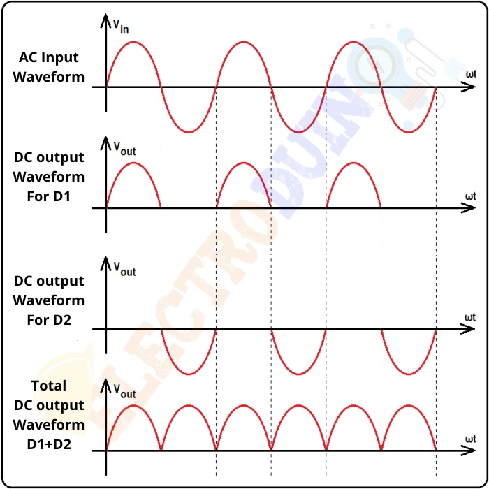
As a result, during the positive half cycle of input AC voltage, diode D1 conducts, and during the negative half cycle of input AC voltage, diode D2 conducts. So, the current appears across the load resistor during both half-cycles (Positive and negative) of input AC voltage and we get DC output voltage across the load resistor. The following figure is the DC output voltage waveform across the load resistor:
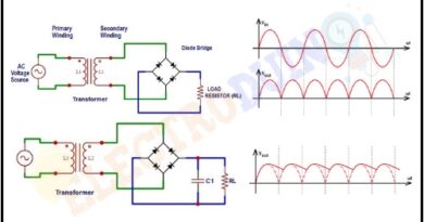
Full Wave Rectifier with Capacitor Filter
By observing the output waveform of the Full Wave Rectifier we can easily understand that the output of the Full Wave Rectifier is not a pure DC voltage. It is a pulsating DC voltage with a lot of ripples that increases to a maximum and then decreases to zero. This type of pulsating DC voltage has no practical applications. So, we need to convert the pulsating DC voltage into pure DC voltage. We can be used a filter to convert the pulsating DC to constant DC. We can be used a filter to convert the pulsating DC to constant DC. Here we use a capacitor filter (C1) which is parallelly connected to the load resistor.
Initially, the capacitor is uncharged. During the first positive half-cycle, the diode D1 is forward biased, at the same time the capacitor starts charging. The capacitor charging continues until the input reaches its peak value (Vp). At this point, the input voltage is equal to capacitor voltage. After the input voltage reaches its peak value then it begins to decrease. When the input voltage is less than Vp, at the same time capacitor starts discharging through the load resistor and supplies the load current, until the next peak arrives.
During the negative half-cycle, the next peak arrives, this time diode D2 conducts, and again the capacitor starts charging until the input reaches its peak value (Vp). When the input voltage is less than Vp, again capacitor starts discharging through the load resistor and supplies the load current, until the next peak arrives.
This process happens again and again. As result, we get a Smooth DC output voltage across the load resistor.
Advantages and Disadvantages of Full Wave Rectifier
Advantages
- High rectifier efficiency: The rectification efficiency of full-wave rectifiers (81.2%) is double of half-wave rectifiers (40.6%). So, this rectifier can converts AC input voltage into DC output voltage more efficiently than the half-wave rectifier.
- No Power loss: This rectifier circuit allows both positive half cycle and negative half cycle of the AC input. Therefore no voltage signal is wasted.
- Low ripples: The output of a full-wave rectifier has lower ripples than a half-wave rectifier. So it produces smooth DC output more than a half-wave rectifier.
Disadvantages
- Complex circuit: More components are used to design and construct this circuit. So, the full-wave rectifier circuit is more complex than a half-wave rectifier circuit.
- High cost: The center-tapped transformer is used in the circuit that is expensive and occupy a large space. So, circuit construction cost is high.