
Arduino PWM Output | Arduino LED Fading
Hello friends! Welcome back to ElectroDuino. This is the Arduino Tutorial #4 – Digital Pin PWM Output | Arduino LED Fading. After understanding Arduino Programing Language | How To Program Arduino in the Arduino Tutorial #3. In this blog, we going to describe what is PWM (Pulse Width Modulation ), Arduino digital pin as PWM output, and Arduino LED Fading using analogWrite() function.
What is PWM (Pulse Width Modulation) Output
Pulse Width Modulation, or PWM, is a technique that is used to get analog results with digital means. This technique is used to create a square wave, a signal switched between on and off. This on-off pattern can simulate voltages in between 5 Volts (ON) and 0 Volts (OFF) by changing the portion of the time the signal spends on versus the time that the signal spends off.
This duration or period is the converse of the Pulse Width Modulation (PWM) frequency. The Arduino’s PWM frequency is about 500Hz, each green line would measure 2 milliseconds. In the Arduino program, we call a function analogWrite(), which is on a scale of 0 – 255. For example, When the analogWrite() value is 255 it means a request for a 100% duty cycle (always ON), and the analogWrite() value is 127 it means a request for a 50% duty cycle (on half the time).
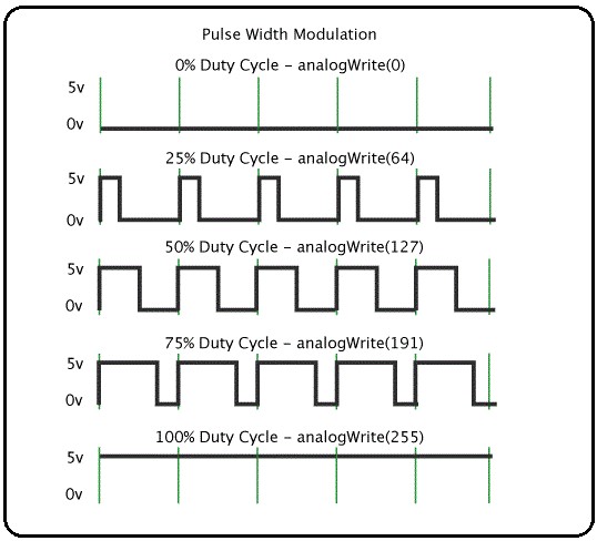
- analogWrite(0) for 0% Duty Cycle
- analogWrite(64) for 25% Duty Cycle
- analogWrite(127) for 50% Duty Cycle
- analogWrite(191) for 75% Duty Cycle
- analogWrite(255) for 100% Duty Cycle
Syntax:
analogWrite(pin, value)
Where, the pin is a PWM pin of Arduino and the value is the duty cycle between 0% – 100%.
Use Digital Pin as PWM Output
We can get analog output from some digital pins of the Arduino board. These digital pins are known as PWM pin. Arduino UNO has 6 PWM pins these are D3, D5, D6, D9, D10, and D11 pin. Also, we need to use the analogWrite() function in Arduino programming to get analog output from these pins. The analog output in the range of 0 to 255. The output switching it off and on very fast and with different ratio between on and off time.
Arduino LED Fading using PWM Output
LED Fade is an interesting lighting project, where the LED intensity or brightness increases from the low to high, and again the intensity or brightness decreases from high to low, it is run gradually. Here we will learn how to make Arduino LED fade using PWM output.
Components Required
| Components Name | Quantity |
| Arduino Uno Board | 1 |
| USB cable for Arduino Uno | 1 |
| LED | 1 |
| 220Ω Resistor | 1 |
| Connecting wire | As required in the circuit diagram |
Arduino LED Fading circuit diagram

Circuit Wiring
| LED Pin | Arduino pin |
| LED positive (+) terminal | connected to Arduino D6 pin through a 220-ohm resistor |
| LED negative (-) terminal | connected to Arduino GND pin |
Arduino LED Fading Program/sketch
/*
Arduino Tutorial #5 – Digital Pin PWM Output | Arduino LED Fading

http://www.electroduino.com
*/

int led = 6;
int brightness = 0;
int fadeAmount = 5;

void setup()

{
  pinMode(led, OUTPUT);
}

void loop()

{
  analogWrite(led, brightness);

  brightness = brightness + fadeAmount;

  if (brightness <= 0 || brightness >= 255)

  {
    fadeAmount = -fadeAmount;
  }

delay(30);
}
Code Description
| Code Line | Description |
int led = 6; |
It is declared your LED pin is connected to Arduino pin 6 and named as led. |
int brightness = 0; |
Take a variable brightness. it is used to set the PWM value. At the starting of the code, we set the value at 0. |
int fadeAmount = 5; |
This is another variable. it is used to increase or decrease the brightness value, Each time through the loop. The increase or decrease of value is 5. |
pinMode(led, OUTPUT); |
Declare pin 6 as an output. |
|
The analogWrite() function that you will be using in the main loop of your code requires two arguments: One, telling the function which pin to write to and the other indicating what PWM value to write. |
brightness = brightness + fadeAmount; |
This line of code is used to Change the brightness for next time through the loop |
|
|
If the LED brightness value is Low (0/off) or High (255/on), then fadeAmount is changed to its negative(-). It means if fadeAmount is 5, then it is set to -5, or If it is -5, then it is set to 5. As a result, brightness changes continuously. |
delay(30); |
It means that wait for 30 milliseconds to see the dimming effect of the LED. |
Output:
As a result, you can see the LED brightness increases from low to high, and again, the brightness decrease from high to low, it is run gradually.


Pingback: Arduino Tutorial #6 - Arduino AnalogRead using Potentiometer. » ElectroDuino
Pingback: Arduino Tutorial #7 – LED Brightness Control Using Potentiometer » ElectroDuino
I simply could not go away your site prior to suggesting that I extremely enjoyed the standard info an individual supply in your visitors? Is gonna be again frequently to check out new posts