
Arduino AnalogRead using Potentiometer
Hello friends! Welcome back to ElectroDuino. This is the Arduino Tutorial #6 – Arduino AnalogRead using Potentiometer. After understanding Use Digital pin as an analog Output | LED Fading in the Arduino Tutorial #5. In this blog, we going to explain Arduino Analog Pins, Arduino analogRead() function, Arduino Potentiometer Circuit diagram, analogRead Program/sketch.
Arduino Uno Analog Pins
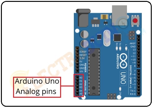
The microcontroller chip of the Arduino board has six analog pins, these are “A0”, “A1”, “A2”, “A3”, “A4”, and “A5”. Each pin has a 10-bit analog-to-digital converter (ADC), it means each pin can store 0 – 1023 (2^10) values. These pins can read the changing of voltage and convert it into integer values between 0 and 1023. Where “0” will be representing the 0 volts (ground) and “1023” will be representing 5 volts (operating voltage). So, the per unit (0-1023) representing the 0.0049 volts (4.9 mW).
analogRead() function
In Arduino programming, we will use an AnalogRead function that is used to measure the voltage between 0 to 5 volts and convert this voltage into integer values between 0 and 1023.
- The analogRead syntax is :
int data = analogRead(int pin);
Arduino AnalogRead using Potentiometer
In this part, we will explain how to connect Potentiometer to Arduino Uno and read the potentiometer analog output using the analogRead() function. Also, print the output value on the Serial Monitor of the Arduino IDE software.
Components Required
| Components Name | Quantity |
| Arduino Uno R3 | 1 |
| USB cable for Arduino Uno | 1 |
| 10k Potentiometer | 1 |
| Breadboard | 1 |
| Connecting wire | As required in the circuit diagram |
What is potentiometer
The potentiometer is a 3 terminal manually adjustable variable resistor. It is also known as “POT”. A potentiometer is a passive electronic component. Potentiometers are mainly constructed with a resistive element and a wiper which sliding on this element when rotated the knob. Also, it has three terminals among which two are fixed and one is variable. The two fixed terminals(1 & 3) of the potentiometer are connected to both ends of the resistive element and the center terminal (2) is connected to the sliding wiper. The resistance of the potentiometer is changed when the wiper is moved over the resistive element.

Here we using a 10k ohm pot. Its resistance can change from 0 to 10 k ohm. When Potentiometer pin 1 connects to + 5v supply and Pin 3 connects to the ground, then we get analog voltage at pin 2.
When the pot shaft is turned all the way in one direction, there are 0 volts going to the pin, and the input value is 0. When the pot shaft is turned all the way in the opposite direction, there are 5 volts going to the pin and the input value is 1023.
Arduino Potentiometer Circuit diagram
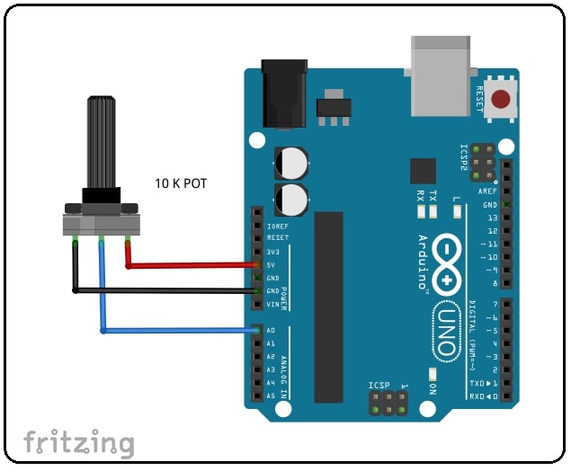
Circuit Wiring
| Potentiometer Pins | Arduino Pins |
| Potentiometer terminal 1 | 5v pin |
| Potentiometer terminal 2 | analog pin “A0” |
| Potentiometer terminal 3 | GND pin |
Arduino AnalogRead Program/sketch
/*
Arduino Tutorial #6 -Analog Data Read using Potentiometer.
http://www.electroduino.com
*/

void setup()
 {
  Serial.begin(9600);
 }

void loop()
 {
  int sensorValue = analogRead(A0);
  Serial.println(sensorValue);
  delay(1);
 }
Code Description
| Code Line | Description |
Serial.begin(9600); |
This function is used to begin serial communication, at 9600 bits of data per second, between your Arduino board and your computer. |
int sensorValue = analogRead(A0); |
This line is the main function of the code. It is used to read output value from the potentiometer and That output value is stored in the “sensorValue” variable in the range between 0 to 1023. |
Serial.println(sensorValue); |
This command is used to print the output value on your Arduino IDE software serial monitor window. |
delay(1); |
wait for 1 millisecond to see the dimming effect |
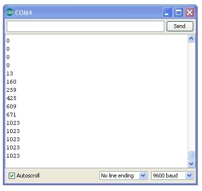
Arduino analogRead( ) Output Result
As a result, you can see the potentiometer output value on your Arduino IDE serial monitor window. The output value changes from 0 to 1023 according to the rotation of the potentiometer Knob.


Pingback: Arduino Tutorial #7 – LED Brightness Control Using Potentiometer » ElectroDuino