IR Remote Control Home Automation using Arduino and TSOP1738
Hello friends! Welcome back to ElectroDuino. This blog is based on IR Remote Control Home Automation using Arduino, TV Remote, and TSOP1738. Here we will discuss Introduction to IR Remote Controlled Home Automation System, Project Concept, Block Diagram, components required, circuit diagram, working principle, and Arduino code.
Introduction
In this modern-day, every home has a TV, DVD, Air Condition, or MP3 player, which is controlled wirelessly using the remote. These remote are communicate with these devices using IR-based wireless communication. In this project, we will control the home appliances by the DVD remote using this wireless communication technique.
Project Concept
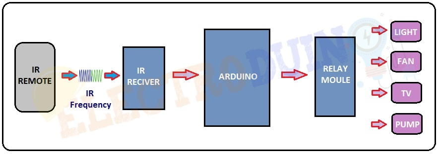
The key components of the project are Arduino, TSOP1738 IR Reciever, DVD Remote, 4 Channel Relay Module. Where Arduino is the main microcontroller of the project that’s controlled all other components. TSOP1738 is an IR Receiver sensor, that can detect 38 kHz IR frequency coming from the IR remote. Here we have used a remote to control home devices. A Relay Module is an electrically operated switch. Which is used to control AC devices. Here we have used a 4-channel relay module to control 4 devices.
Block Diagram of IR Remote Control Home Automation using Arduino and TSOP1738
Components Required
| Components Name | Quantity |
| Arduino UNO | 1 |
| TSOP 1738 IR Receiver sensor | 1 |
| 4 Channel Relay Module | 1 |
| DVD Remote (any IR Remote) | 1 |
| AC Bulb with Holder and Wire | 4 |
| PCB Prototyping board | 1 |
| 12V DC Power supply | 1 |
| 220V AC Power supply | |
| Connecting wires | As required in the circuit diagram |
Tools Required
| Tools Name | Quantity |
| Soldering Iron | 1 |
| Soldering wire | 1 |
| Soldering flux | 1 |
| Soldering stand | 1 |
| Multimeter | 1 |
| Desoldering pump | 1 |
| Wirecutter | 1 |
| Screwdriver | 1 |
“IRremote” library download from https://github.com/z3t0/Arduino-IRremote
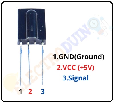
TSOP 1738 IR Receiver sensor
TSOP1738 is an IR Receiver sensor, it is consists of a Photodetector and signal demodulator. It can detect 38 kHz IR frequency coming from the IR remote. The TSOP1738 sensor operates on 5V dc power supply and consumes around 5mA to operate. This sensor has 3 terminals, these are GND(ground), VCC(+5v), and Signal pin. we need to connect the signal pin to a microcontroller to read the received data by the sensor.
IR Remote
IR(InfraRed) remote is used to control devices IR based wireless communication. It emits InfraRed light when we press the button. Each button can emit a particular frequency of IR light. The main feature of IR Remote is that it can control a specific device. For example, a TV remote can control a particular TV.
Circuit Diagram of IR Remote Control Home Automation using Arduino, TV Remote, and TSOP1738
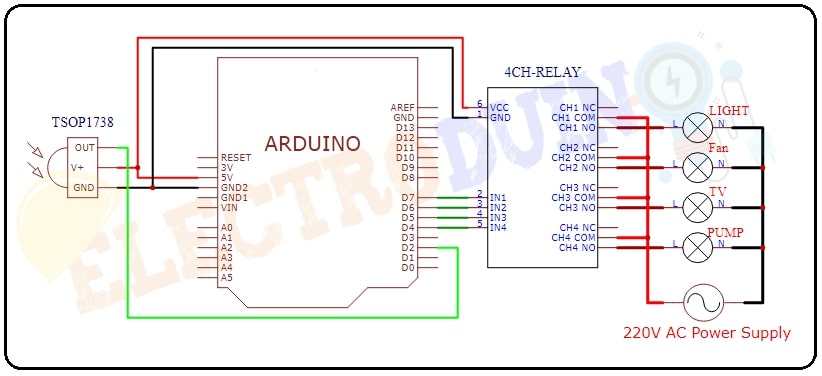
Circuit Wiring
| Components Pin | Arduino pin |
TSOP 1738 IR Receiver and Relay Module Vcc Pin | 5V pin |
| TSOP 1738 IR Receiver and Relay Module GND Pin | GND Pin |
| TSOP 1738 IR Receiver Out Pin | Digital Pin “D2” |
| 4 Channel Relay Modules IN1, IN2, IN3, IN4 | Respectively Digital Pin “D7”, “D6”, “D5”, “D4”, |
| 12V Power supply | External DC Power supply for operating Arduino |
Working Principle IR Remote control home automation
In this project, we have used a simple Method for control (ON/OFF) a single home appliance device by a single button of Remote, this Method is known as Toggle [EVEN ODD] Method. As an example, we can turn ON and OFF of a device using the Remote button “1“.
At first, we will identify 4 buttons of the remote for controlling 4 devices. Here we have used 1, 2, 3, 4, and Power button of the IR remote. The power button is used to turn ON or OFF all devices same time.
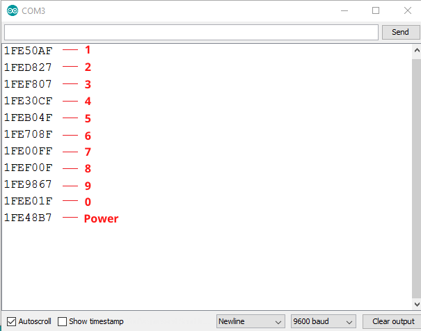
When we pressed any button of the remote, the IR LED of the remote sends a unique encoded signal. The TSOP1738 IR Receiver sensor received this signal and send it to the Arduino. First of all, the Arduino decodes the signal and converts it into a hex value, and store the value into the variable. For that, we need to use a special library called “IR remote” in the Arduino program. Then, the Arduino compares the decode hex value with the predefined hex value of the pressed button. If this value is matching then Arduino sends an operating voltage to the relay module for turns ON the device.
If we again press the same button then it sends the same code. So, Arduino gets again the same code and the Arduino compares the decode hex value with the predefined hex value of the pressed button like before. But this time Arduino stop sending operating voltage to the Relay module and turns OFF the device because of Toggling the bit [EVEN ODD] (i%2).
IR DVD Remote HEX Value Decoding using Tshop1738 and Arduino
Arduino Code for IR Remote Control Home Automation
#include <IRremote.h> //Include libraries for IRremote
const int IRpin= 2; // connect Tshop1738 sensor to arduino pin 3

IRrecv irrecv(IRpin);
decode_results results;

#define IN1 7
#define IN2 6
#define IN3 5
#define IN4 4

bool i=false;
bool j=false;
bool k=false;
bool l=false;
bool m=false;
void setup()
{
  Serial.begin(9600);
  pinMode(IN1, OUTPUT);
  pinMode(IN2, OUTPUT);
  pinMode(IN3, OUTPUT);
  pinMode(IN4, OUTPUT);
  irrecv.enableIRIn(); // Start the receiver
  irrecv.blink13(true);

}
void loop()
{
  if (irrecv.decode(&results))
    {
     Serial.println(results.value,HEX);
     delay(100);

     if(results.value==0x1FE50AF)
      {
        i=!i;
        digitalWrite(IN1, i);
      }

     if(results.value==0x1FED827)
     {
        j=!j;
        digitalWrite(IN2, j);

       // delay(200);
     }
     if(results.value==0x1FEF807)
     {
        k=!k;
        digitalWrite(IN3, k);

       // delay(200);
     }

     if(results.value==0x1FE30CF)
     {
        l=!l;
        digitalWrite(IN4, l);

       // delay(200);
     }

     if(results.value==0x1FE48B7)
     {
        m=!m;
        digitalWrite(IN1, m);
        digitalWrite(IN2, m);
        digitalWrite(IN3, m);
        digitalWrite(IN4, m);

       // delay(200);
     }
     irrecv.resume(); // Receive the next value
     //delay(100);
   }
}