
Arduino Tutorial #1 – Introduction to Arduino Board
Hello friends! Welcome back to ElectroDuino. This blog is base on Arduino tutorial/course #1 – Introduction to Arduino Board. Here, we will learn about the most popular prototype platform (open-source), known as Arduino. In this tutorial, we will discuss what is Arduino board, Board Description, pin configuration, Applications, and types of Arduino. Let’s begin…
What is Arduino board?
The Arduino is an open-source electronics platform. That makes the interaction between software and hardware to build electronics projects. The Arduino can read the sensor’s output data as input and turn it into an output to control other components like LED, MOTOR, etc. We need a ready-made software to write and upload code to Arduino boards, its called Arduino IDE (Integrated Development Environment).
The IDII Master’s student Hernando Barragán created the development platform under the supervision of Massimo Banzi and Casey Reas in the thesis project in 2003.
In this tutorial, we will discuss the most popular and most used board in the Arduino board family. This is the Arduino Uno.
What is Arduino Uno?
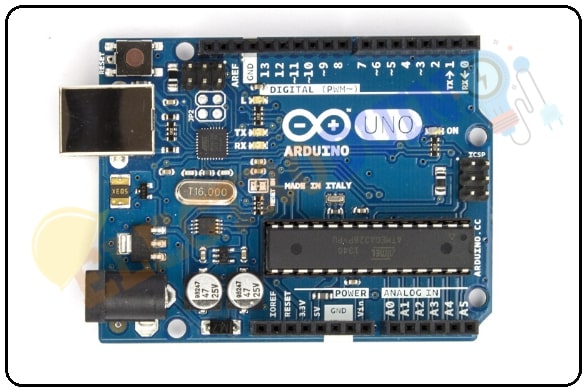
Arduino Uno is an open-source electronics platform based on the 8-bit ATmega328P microcontroller chip. It is easy to use as well as easy to upload programming. It has 14 digital input/output pins and 6 analog input pins, these pins can read the sensor’s output data as input and turn it into an output to control other components like LED, MOTOR, etc. It has a 16 MHz Crystal Oscillator, that helps Arduino in dealing with time issues like, calculate time.
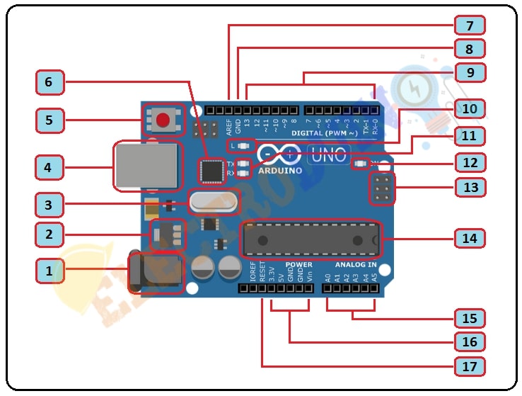
Arduino UNO Description
|
Sl.No. |
Parts Name |
Parts Description |
| 1 | Barrel Connector | This connector provides external voltage to operate the Arduino board. The input Voltage Limit is 6-20V DC. |
| 2 | Voltage Regulator | The voltage regulator controls the input voltage. It provides required DC voltage to the processor and other elements. |
| 3 | Crystal Oscillator | This is a 16 MHz Crystal Oscillator. It tells us that the frequency of the Crystal Oscillator is 16,000,000 Hertz or 16 MHz. So, it helps Arduino in dealing with time issues like, calculate time. |
| 4 | USB Port | USB Port helps connect the Arduino board to your computer by using the USB cable. it is used to upload programming code to the Arduino board from your computer. Also, it can be used as an External power input port to operate Arduino. |
| 5 | Reset Button | When we push this switch its connects the microcontroller Resets pin to the ground. This switch help reset your Arduino board, to start your program from the beginning. |
| 6 | ATmega16 | Atmega16U2 provides a pathway for serial communication using USB com drivers. |
| 7 | AREF | AREF is called Analog Reference. This pin is used for providing a reference voltage (between 0 and 5 Volts) to the analog inputs. |
| 8,16 | Power Pin | 3.3v – Supply 3.3 output volt. 5v – Supply 5 output volt. GND – 3 ground pins are available on the board. 3.3v and 5v output are used to provide power to other sensors and circuit boards which operated on 3.3v and 5v power supply. VIN – Also, It is the input voltage provided to the Arduino Board. |
| 9 | Digital I/O pins | The Arduino UNO board has 14 Digital I/O pins(0-13). These pins can work as digital input pins to read logic values 0 or 1. Or it can work as digital output pins to drive different modules like LEDs, relays, etc. |
| 10 | LED | This LED is connected to the digital pin 13. when pin output is HIGH it will turn ON and for LOW it will turn OFF. |
| 11 | TX and RX LED | The TX and RX LEDs are connected to the Serial communication pin 1 and 0 respectively. These LEDs indicate serial communication. TX led flashes with different speeds while sending the serial data. RX led flashes with different speeds while receiving the serial data. |
| 12 | Power LED indicator | This LED is the power supply indicator. when Arduino connects with a power source then it will turn ON. |
| 13 | ICSP pin | ICSP stands for In-Circuit Serial Programming. This pin is a tiny programming header for the Arduino. It consists of MOSI, MISO, SCK, RESET, VCC, and GND. These pins enable the user to program the Arduino boards. |
| 14 | Microcontroller | Every Arduino board has its own microcontroller. The main IC (integrated circuit) on the Arduino is slightly different from board to board Which makes Arduino different from each other. In Arduino UNO it is Atmega328. ATmega328P – 8-bit AVR family microcontroller. It is a 40 pin IC. |
| 15 | Analog I/O pins | The Arduino UNO board has 6 Analog I/O pins(A0-A5). These pins can read the analog signals from an analog sensor and convert it into a digital value that can be read by the microcontroller. Used to provide analog input in the range of 0-5V |
| 17 | Reset Pin | Also, we can use this pin to reset the microcontroller when it connects to the ground pin. |
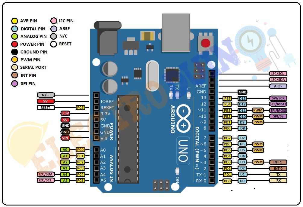
Arduino UNO Pin Diagram
|
Pin Category |
Pin Name |
Details |
|
AVR Pin |
PD (0-7) , PB(0-5) , PC (0-6) |
These pin numbers indicate the main microcontroller ATmega328P pins. |
|
Digital pin |
D0 – D13 |
These are the digital input/output pins. Logic data is 0 or 1. |
|
Analog Pins |
A0 – A5 |
These are the Analog input/output pins. input voltage range 0-5v. |
|
Power pin. |
3.3v, 5v, VIN, IOREF |
3.3v – output voltage +3.3v |
|
Ground pin |
GND, |
GND – ground (-) |
|
PWM pin |
D3, D5, D6, D9, D11 |
Pulse Width Modulation or PWM is a technique that is used to getting analog results with digital means. Arduino uses this pin to control the brightness of an LED, speed control of DC motor, controlling a servo motor. |
|
Serial Port |
D0(Rx), D1(Tx) |
Pins 0 and 1 are used for communication with the computer or other devices. This pin also is known as UART or USART. |
|
INT Pin |
D2, D3 |
Interrupt Pins are very useful in Arduino programs as it helps in solving timing problems. It also useful in Arduino programs as it helps in solving timing problems. |
|
SPI Pin |
D10 (SS), D11 (MOSI), D12 (MISO) and D13 (SCK) |
These pins are used for SPI communication. We can use SPI Protocol for communication between two Arduinos. One Arduino will act as Master and another one will act as Slave |
|
I2C pin |
A4, A5 |
Used for Two-Wire communication. |
|
AREF |
|
AREF is called Analog Reference. This pin is used for providing a reference voltage (between 0 and 5 Volts) to the analog inputs. |
|
N/C |
|
No Connection. It not use. |
|
RESET |
|
we can use this pin to reset the microcontroller when it connects to the ground pin. |
Arduino Uno Specifications
- Microcontroller: ATmega328P – 8-bit AVR family microcontroller
- Operating Voltage: 5V
- Recommended Input Voltage: 7-12V
- Input Voltage ranges: 6-20V
- Analog Input Pins: 6 (A0 – A5)
- Digital I/O Pins: 14 (D0 – D13)
- PWM Digital I/O Pins: 6
- DC Current on I/O Pins: 40 mA
- DC Current on 3.3V Pin: 50 mA
- Flash Memory: 32 KB (0.5 KB is used for Bootloader)
- SRAM: 2 KB
- EEPROM: 1 KB
- Frequency (Clock Speed) : 16 MHz
- LED_BUILTIN: 13
- Length: 68.6 mm
- Width: 58.4 mm
- Weight: 25 g
Arduino Uno Applications
- Used in Do-it-Yourself projects prototyping.
- Security and Defense System
- Digital Electronics and Robotics
- Development of Medical Instrument
- Used in Home Automation
- Industrial Automation
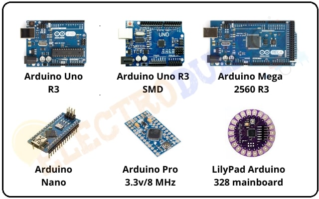
Different Type of Arduino boards
So many types of Arduino boards are available In the market. Every board comes with a different specification. Here we discuss the most popular and most used boards.
|
Board Name |
Operating Voltage |
Clock Speed |
Microcontroller |
Digital i/o |
Analog Inputs |
PWM |
UART |
Programming Interface |
|
Arduino Uno R3 |
5V |
16MHz |
ATmega328P |
14 |
6 |
6 |
1 |
USB via ATMega16U2 |
|
Arduino Uno R3 SMD |
5V |
16MHz |
ATmega328P |
14 |
6 |
6 |
1 |
USB via ATMega16U2 |
|
Arduino Mega 2560 R3 |
5V |
16MHz |
ATmega2560 |
54 |
16 |
14 |
4 |
USB via ATMega16U2B |
|
Arduino Nano |
5V |
16 MHz |
ATmega328P |
14 |
8 |
6 |
1 |
USB via ATMega16U2B |
|
Arduino Pro 3.3v/8 MHz |
3.3V |
8MHz |
ATmega328P |
14 |
6 |
6 |
1 |
FTDI-Compatible Header |
|
LilyPad Arduino 328 mainboard |
3.3V |
8MHz |
ATmega328P |
14 |
6 |
6 |
1 |
FTDI-Compatible Header |

