
Adjustable DC Power Supply Circuit using LM317
Hello friends! Welcome back to ElectroDuino. This blog is based on the Adjustable DC Power Supply Circuit using LM317. Here we will discuss Introduction to Adjustable DC Power Supply, Project Concept, Block Diagram, Components Required, Circuit Diagram, Working Principle, and Output Voltage Calculation.
Introduction
We know that different types of electronic circuits operate on different value DC power supplies. For this reason, we need different value power adaptors or voltage regulator IC to power up the circuits. The 78XX (7805, 7806, 7812, etc) series voltage regulator ICs provide a constant and fixed value positive DC power supply, and the 79XX (7905, 7906, 7912, etc) series provide the negative power supply. In this tutorial, we will build an Adjustable DC Power Supply Circuit using LM317. This circuit provides an adjustable output voltage range of 1.25 V to 37 V with a 1.5A max current, which is suitable to power up the different electronic circuits.
Project Concept
This circuit consists of a few key components which are the main foundation of the circuit. These key components are Step down transformer, Bridge Rectifier, Smoothing Capacitor, LM317 Variable Voltage Regulator, and potentiometer. The Step-down transformer is used to steps down the high voltage AC mains input into low voltage AC output. The Bridge Rectifier circuit converts this low voltage AC into pulsating DC voltage output. The Smoothing Capacitor filters this DC voltage and produces pure Dc voltage. This DC voltage goes to the LM317 variable Voltage regulator IC as input. The output voltage of the IC can be adjusted by the potentiometer, which is connected to the Adjust pin of the IC.
Block Diagram of Adjustable DC Power Supply Circuit using LM317

Components Required
| Components Name | Quantity |
| LM317 Voltage Regulator IC (U1) | 1 |
| 220V to 24V 1.5A Step-down Transformer | 1 |
| 1N4007 Diode (D1, D2, D3, D4, D5, and D6,) | 6 |
| 10K ohm Potentiometer (R1) | 1 |
| 220 ohm Resistor (R2) | 1 |
| 2200µF Capacitor (C1) | 1 |
| 0.1µF Capacitor (C2, C3) | 2 |
| 10µF Capacitor (C4) | 1 |
| PCB board | 1 |
| Connecting Wire | As required in the circuit diagram |
Tools Required
| Tools Name | Quantity |
| Soldering Iron | 1 |
| Soldering wire | 1 |
| Soldering flux | 1 |
| Soldering stand | 1 |
| Multimeter | 1 |
| Desoldering pump | 1 |
| Wirecutter | 1 |
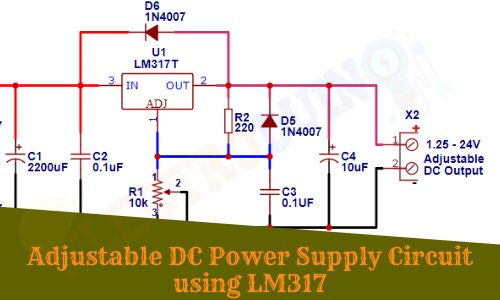
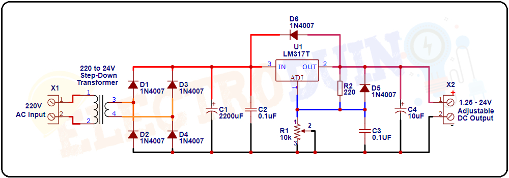
Circuit/Schematic Diagram of Adjustable DC Power Supply Circuit using LM317
Working Principle
According to the LM317 datasheet, this voltage regulator Output voltage can be set to range from 1.25V to 37V, and the max output current is 1.5A. Here, we have used 220V to 24V 1.5A step-down transformer which converts 220v high voltage AC input into 30v low voltage AC output. We need to convert this low voltage AC output into a 24V DC voltage. For this reason, we have used four 1N4007 Diodes to make a Bridge rectifier circuit that produces a 30v pulsating DC voltage as output from 24V AC voltage input. But this is a pulsating DC voltage that consists of AC ripples, so we connect a 2200µF capacitor (C1), and 0.1µF capacitor (C2) to the output of the bridge rectifier, which filters the pulsating DC voltage and produces pure 24v DC voltage.
This pure DC voltage goes to the Vin pin of the LM317 voltage regulator IC as input. A 10K potentiometer (R1) is connected to the ADJUST pin (ADJ pin) of the LM317 IC. 220 ohm resistor (R2) is connected between the ADJUST pin (ADJ pin) and Vout pin of the LM317 IC. The ADJUST pin (ADJ pin) takes feedback voltage and current through variable Resistor (R1) and R2 resistor. A 1N4007 diode (D1) connected between Vin pin and Vout pin, Vin pin takes feedback from the output pin Vout through this diode (D5). Another 1N4007 Diode (D6) is connected at the output which provides reverse voltage protection. The 0.1uf capacitor (C3) bypassing the ADJUST pin to the ground will improve the ripple rejection capability. A 10uf capacitor (C4) has connected at the end of the circuit to make the output voltage more stable. Generally, the output voltage range can be adjusted by rotating the control shaft of the potentiometer (R1).
Output Voltage Calculation for LM317
The LM317 has an input voltage range of 3 to 40v DC and an adjustable output voltage range of 1.25v to 37v DC. We can adjust the output voltage of the LM317 by two external resistors connected through the adjustable pin.
Note that, The output voltage will depend on the external resistor only, but the input voltage should always be greater than (minimum of 3v) the required output voltage”
According to the datasheet, the recommended value of resistor R2 is 220Ω or 240Ω (I use the 220Ω) and we can vary the resistor R1.
The output voltage of the LM317 IC can be calculated by the following formula,
Vout = 1.25 {1 + (R2 / R1)}