Hello friends! Welcome back to ElectroDuino. This blog is base on How to Make a Single Axis Solar Tracking System. Here we will discuss Introduction to Single Axis Solar Tracking System, Project Concept, Block Diagram, components required, circuit diagram, working principle.
In modern days continuously increased the use of renewable energy sources for generating electric power. The most using renewable energy source is Solar power. Solar power generation is a process where the transformation of Sunlight (daylight) into power using Solar Panel/Plate. The amount of transformation energy depends on the amount of sunlight falling on the Solar Panel. Basically, Solar Panels are fixed devices that are fixed at a position. So, in this case, the solar panel can produce maximum power when the sun is staying in front of it. In this project, we will construct a system that can help the Solar panels to follow the sun movement and generate maximum power.
Project Concept
Single Axis Solar Tracking System is a device that rotates the solar panel one axis and follows the sun movement. Here we are using two LDRs to measure the intensity of light falling, it is placed on both sides of the solar plate. Also, we will use a dual Op-Amp voltage comparator IC. This IC compares the LDRs value and provides output to the transistor to control the motor direction. If anyone of these LDRs measures intensity light greater than other LDR, then the solar panel will rotate the direction of higher intensity sensing LDR by the motor. as an example, if LDR 1 measures the high light intensity and LDR 2 measures the low light intensity, then the solar panel will rotate the direction of LDR 1 by the motor.
Single Axis Solar Tracking System using LM358 Block diagram
Block Diagram of Single Axis Solar Tracking System Using LM358
Components Required
Components Name
Quantity
LM358 IC
1
Q1 & Q2 Transistor BC547
2
Q3 & Q4 Transistor BC557
2
LDR ( Light Dependent Resistor)
2
R1, R2 Resistor 1K ohm
2
R3, R4 Resistor 10K ohm
2
RV1 Potentiometer 10K ohm
1
D1,D2,D3 & D4 Diode 1N4007
4
12v DC Motor
1
Power Supply 12v
1
Tools Required
Tools Name
Quantity
Soldering Iron
1
Soldering wire
1
Soldering flux
1
Soldering stand
1
Multimeter
1
Desoldering pump
1
Wirecutter
1
Component Explanation
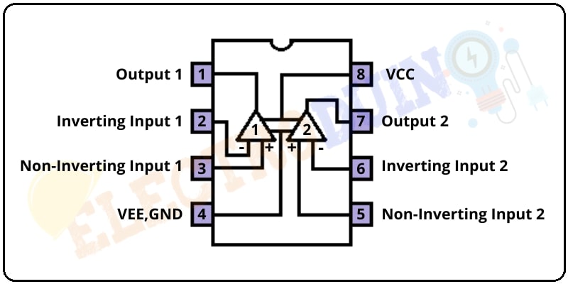
Op-Amp LM358 IC
LM358 is one type of dual-channel operational amplifier (Op-Amp). It consists of two independent, high-gain, frequency-compensated operational amplifiers (Op-Amp). The IC is designed like that the Op-Amps are operating from a single supply or split supplies over a wide range of voltages. The IC’s each op-amp can handle 3-32V DC supply & current up to 20mA. The LM358 Op-Amp is an 8 pin IC available in different packages. The most used package is an 8 pin dip package. The applications of the LM358 IC are used in op-amp circuits, DC gain blocks, and transducer amplifiers.
LM358 Op-Amp IC Internal Structure
BC547 Transistor
The BC547 is an NPN Bipolar Junction Transistor. This is normally used as a switch and amplifier. In this circuit, the transistor is used as a switch. The smaller amount of current applied at the base, it can control the larger amount of currents at collector and emitter.
BC557 Transistor
The BC547 is a PNP Bipolar Junction Transistor. This is normally used as a switch and amplifier. When the ground(0) voltage is applied on the base, then the collector and emitter will be closed (Forward biased) and when the positive voltage is applied on the base, then the collector and emitter will be opened (Reverse biased)
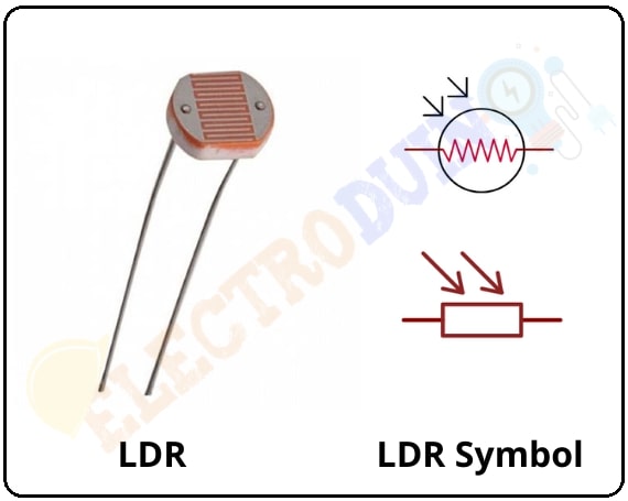
LDR (Light Dependent Resistor)
The LDR or Light Dependent Resistor is a variable resistor. It is also known as a photoresistor. These LDR, Light Dependent Resistor or Photoresistor works on the principle of “Photo Conductivity”. The LDR resistance is change depends on the light intensity falls on the LDR surface. When light falls on the surface of the LDR then the resistance of the LDR decreases and increases the conductance of the element. When no light falls on the surface of the LDR then the resistance of the LDR is high and decreases the conductance of the element.
LDR or Light Dependent Resistor & Symbol
Single Axis Solar Tracking System Circuit Diagram
Circuit diagram of Single Axis Solar Tracking System Using LM358
Circuit Wiring
LDR1 is connected with R1 (10K) in series. The connection point of LDR1 and R1 is the Output of the LDR1, which is connected to pin 3 of the LM358 IC. Pin 3 is the non-inverting input terminal of the LM358 IC’s Op-Amp1.
Similarly, LDR2 is connected with R2 (10K) in series. The connection point of LDR2 and R2 is the Output of the LDR2, which is connected to pin 5 of the LM358 IC. Pin 5 is the non-inverting input terminal of the LM358 IC’s Op-Amp2.
The 10K Variable resistor (RV1) fixed terminal 1 is connected to Vcc and fixed terminal 2 is connected to the ground. The Variable terminal of the Variable resistor (RV1) is connected to IC pin 2 and 6. Pin 2 and 6 are the inverting input terminals of the IC’s Op-Amp 1 and Op-Amp 2 respectively.
The Op-Amp 1 output pin (IC pin 1) is connected to the base terminal of the transistor Q1 and Q3, and the Op-Amp 2 output pin (IC pin 7) is connected to the base terminal of the transistor Q2 and Q4.
Transistor Q1 and Q2 collector terminal is connected with Vcc, and Transistor Q3 and Q4 collector terminal is connected with Ground.
The Emitter terminal of the transistor Q1 and Q3 both are shorted and connected to the motor terminal through the connection point of diode D1 and D3. The Emitter terminal of the transistor Q2 and Q4 both are shorted and connected to the motor terminal through the connection point of diode D2 and D4.
Working of Single Axis Solar Tracking System using LM358
LM358 is the main controller that controls the whole system. Here its works as a voltage comparator, the output of the voltage comparator will be High when the voltage at the non-inverting input terminal (+) is greater than the voltage at the inverting input terminal (-).
When no light falls on the LDR surface its resistance is high, then all voltage is allocated across the LDR and output is Low(ground). When light falls on the LDR surface its resistance is low, then the all voltage is allocated across the resistor and output is High(VCC).
The variable resistor is used to set the reference voltage at the Inverting (-) terminal of the Op-Amp 1 and Op-Amp2.
The transistors BC547 and BC557 are making an H-Bridge formed, which is control the motor direction.
When the light falls increases on an LDR, then the output voltage of LDR is increasing. So, the voltage at the non-inverting (+) terminal also increases, when this voltage is greater than the reference voltage then the output of the Op-Amp goes HIGH.
This system works in 4 conditions:
If the output of Op-Amp 1 (U1:1)isHigh and the output of Op-Amp 2 (U1:2) is Low. In this case, transistors Q1 and Q4 will turn on. As a result, the current flows through the motor, and the motor starts to rotate in the clockwise direction.
Working of Solar Tracker Case 1
If the output of Op-Amp 2 (U1:2) is High and the output of Op-Amp 1 (U1:1) is Low. In this case, transistors Q2 and Q3 will turn on. As a result, the current flows through the motor, and the motor starts Working of Solar Tracker Case 2to rotate in the anticlockwise direction.
If the output of both Op-Amps is low, transistors Q3 and Q4 turn on, but no current will flow through the motor. So, the motor will be stopped.
Working of Solar Tracker Case 3
If the output of both Op-Amps is High, transistors Q1 and Q2 turn on, but no current will flow through the motor. So, the motor will be stopped.


Pingback: Dual Axis Solar Tracker using LM339 and L293D motor driver IC »