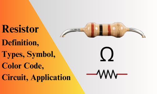
Resistor: Definition, Types, Symbol, Color Code, Circuit, Application
Resistors are fundamental electronic components used to control the flow of electric current in circuits. They are widely used in various applications, from simple devices to complex systems. They come in various shapes, sizes, and materials, making them versatile tools for a wide range of applications. In this article, we will discuss What is a Resistor, SI Unit, Symbols, Types, Color Coding Systems, Properties, Series and Parallel connections, and Applications.
What is a Resistor?
Definition: A resistor is a two-terminal passive electronic component that resists or opposes the flow of electric current in electrical circuits.
Its primary function is to control the amount of current flowing through a circuit by providing resistance. It is designed to dissipate electrical energy in the form of heat. By blocking the flow of current, resistors help regulate voltage levels, control current intensity, and protect components from excessive current. Basically, the resistors are made of copper wires which are coiled around a ceramic rod and the outer part is coated with an insulating paint.
What is the SI Unit of Resistor?
The SI unit of resistance is the ohm, symbolized by the Greek letter “Ω.” Named after the German physicist Georg Simon Ohm.
What is Ohm: The ohm- represents the amount of resistance a material offers to the flow of electric current. It is a measure of the opposition encountered by the electrons as they move through a conductor.
The ohm is a derived unit, calculated using basic units of the SI system. It can be expressed as volts per ampere (V/A) or joules per coulomb (J/C). In practical terms, a 1ohm or 1Ω resistor allows a current of one ampere (1A) to flow through it when a voltage of one volt (1V) is applied.
where, 1Ω = 1V/1A or 1J/1C
The resistors which have high resistance values can be represented through Kilo-ohms (KΩ) & Meg-ohms (MΩ). For example, if the resistor value is 100 000 ohms then it can be represented as 100k ohms, and if the resistor with 1000 000 ohms then it can be represented as 1Mega ohms.
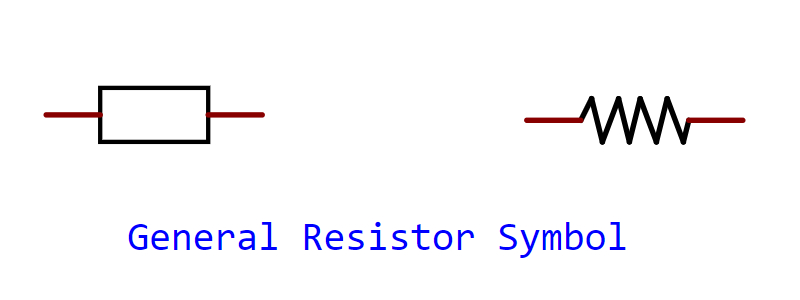
Symbol of Resistor
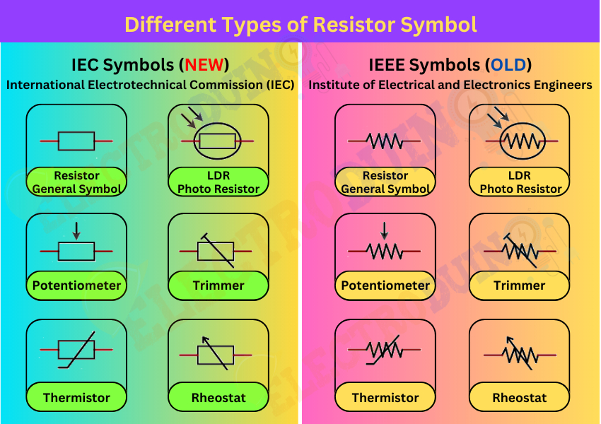
The Circuit symbol or Schematic symbol of a resistor is a simple and commonly used graphical depiction in electrical circuit diagrams. Basically, the standardized Resistor symbol is a rectangular shape with two terminals, one at each end.
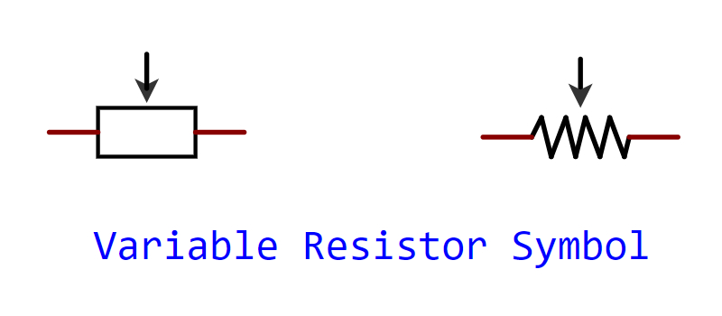
Variable resistors, such as potentiometers or rheostats, have a slightly different symbol. They are represented by a resistor symbol with an arrow pointing to the rectangular shape, indicating the adjustable or variable nature of the component.
International Standards: The symbol of a resistor is based on international standards, such as the International Electrotechnical Commission (IEC) and Institute of Electrical and Electronics Engineers (IEEE) standards. These standards ensure consistency and clarity in circuit diagrams across different countries and industries.
Type of Resistor
They come in various shapes, sizes, and materials, making them versatile tools for a wide range of applications. There are various types of resistors available, each designed to suit specific applications.

There are various types of resistors, each designed for specific applications. Basically, there are two Types of Resistors:
- Linear Resistor
- Nonlinear Resistor
1. Linear Resistor
Linear resistors are a fundamental component in electronic circuits, serving as essential elements for controlling current and voltage. They possess a linear relationship between voltage and current, meaning the current flowing through them is directly proportional to the voltage applied across them.
There are two types of linear resistors that have linear properties:
- Fixed resistors
- Variable Resistors
A. Fixed resistors
The fixed resistors offer a consistent resistance value that remains unaltered during operation. They are fabricated with predetermined resistance levels, which can range from a few ohms to megohms, and serve as building blocks for electronic systems. Fixed resistors come in several types, some common types are:
- Carbon Composition
- Wire Wound Resistor
- Thick Film Resistor
- Thin Film Resistor
B. Variable Resistors
Variable resistors are essential components in electronic circuits that offer the ability to adjust and control resistance. Their variable nature allows for precise regulation of current or voltage levels within a circuit, making them versatile tools for numerous applications. Some common types of Variable Resistors are:
- Potentiometer
- Rheostat
- Trimmer Resistor
2. Nonlinear Resistors
Nonlinear resistors, also known as variable resistors or non-ohmic resistors, deviate from the linear relationship between voltage and current exhibited by traditional, linear resistors. Unlike their linear counterparts, which maintain a constant resistance regardless of voltage or current changes, nonlinear resistors showcase varying resistance values in response to fluctuations in voltage or current. Some common types of Nonlinear resistors:
- Thermistor
- Photo Resistor
- Varistor Resistor
- Surface Mount Resistor
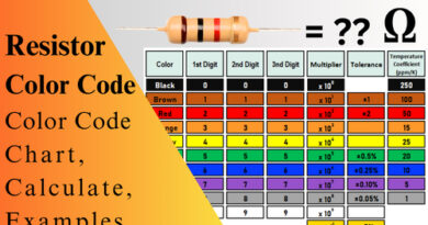
Resistor Color Code
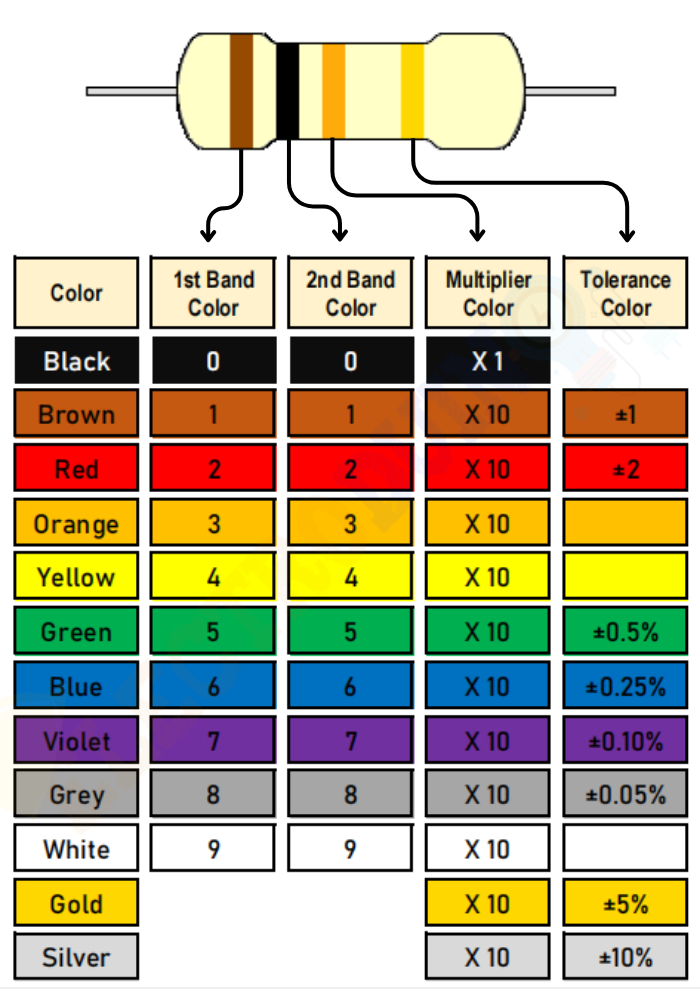
Resistors typically have their resistance value indicated by colored bands on their bodies. The color code consists of a series of colored bands printed on the resistor body. Each color represents a specific digit or multiplier, and by decoding the color bands, you can determine the resistance value. The color coding system follows a specific pattern:
- The first band represents the first digit of the resistance value.
- The second band represents the second digit.
- The third band indicates the number of zeros to be added after the first two digits to obtain the resistance value.
- The fourth band (if present) represents the tolerance, which specifies the acceptable range of variation from the nominal resistance value.
The most common color code follows the pattern: black, brown, red, orange, yellow, green, blue, violet, gray, and white.
Example:
100 ohm Resistor Color Code: The resistor with color bands Brown-Black-Brown-Gold would have a resistance value of 1,00 ohms (10 x 10), with a tolerance of ±5%.
1k ohm Resistor Color Code: The resistor with color bands brown-black-red-gold would have a resistance value of 1,000 ohms (10 x 100), with a tolerance of ±5%.
10K ohm Resistor Color Code: The resistor with color bands Brown-Black-Ornge-Gold would have a resistance value of 1,0000 ohms or 10K ohm (10 x 1000), with a tolerance of ±5%.
Properties of Resistor
The properties of resistors include resistance tolerance, power rating, temperature coefficient of resistance, and voltage coefficient of resistance. These properties determine the resistor’s performance and suitability for specific applications. Resistors exhibit various characteristics that define their behavior in a circuit. Understanding the characteristics helps engineers select the right resistors for their specific applications. Some essential characteristics include:
- Resistance: The resistance value determines the degree to which a resistor opposes the flow of current. This is the fundamental characteristic of a resistor and determines the amount of current flowing through it. It is crucial to select the appropriate resistance value to ensure desired circuit performance.
- Power Rating: It indicates the maximum amount of power a resistor can safely dissipate without getting damaged. It is essential to choose a resistor with a power rating suitable for the application to avoid overheating or damage.
- Tolerance: Tolerance specifies the acceptable deviation from the nominal resistance value. For example, a resistor with a 10% tolerance and a stated resistance of 100 Ω can have an actual resistance ranging from 90 Ω to 110 Ω.
- Temperature Coefficient of Resistance (TCR): The temperature coefficient of a resistor indicates how its resistance value changes with temperature. It is expressed in parts per million per degree Celsius (ppm/°C) and helps predict the resistor’s behavior in different temperature conditions.
- Noise: Resistors generate thermal noise due to random fluctuations in the flow of electrons. It is essential to consider noise characteristics in sensitive applications.
- Inductance and Capacitance: Resistors have inherent inductance and capacitance properties that can affect circuit behavior at high frequencies.
Resistors in Series and Parallel Connection
Resistors can be connected in series or parallel configurations to achieve specific resistance values or voltage/current distribution.
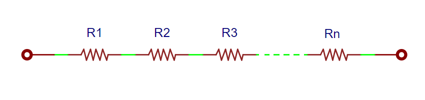
Resistors in Series Connection
When resistors are connected in series, their individual resistances add up to produce a total resistance value. The current flowing through each resistor in a series circuit remains the same, while the voltage across each resistor is proportional to its resistance. The total resistance (Rs) of a series connection can be calculated by summing the individual resistances (R1, R2, R3, …, Rn)
Formulas for Series Resistance:
Rs = R1 + R2 + R3 + … + Rn
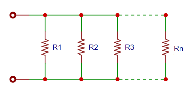
Resistors in Parallel Connection
In a parallel configuration, the total resistance is determined by the reciprocal of the sum of the reciprocals of individual resistances. Each resistor in a parallel circuit experiences the same voltage, while the current across each resistor is inversely proportional to its resistance.
The total resistance (Rp) of a parallel connection can be calculated by using the bellow formula.
Formulas for Parallel Resistance:
1/Rp = 1 / (1/R1 + 1/R2 + 1/R3 + … + 1/Rn)
Applications of Resistor
Resistors are vital components in various electronic circuits. Some common applications include:
- Voltage Dividers: Resistors are used in voltage divider circuits to obtain a desired output voltage from a higher input voltage. This technique is commonly used in level shifting, sensor interfacing, and signal conditioning.
- Current Limiting: By introducing resistance in series with a load, resistors help control the amount of current flowing through the load, thereby protecting it from excessive current.
- Timing Circuits: Resistors, in conjunction with capacitors, form RC timing circuits used in applications such as oscillators, pulse generators, and time delay circuits.
- Feedback Networks: Resistors play a crucial role in feedback networks used in amplifiers, filters, and control systems to stabilize and control circuit behavior.
- Temperature Sensing and Compensation: Thermistors and resistance temperature detectors (RTDs) are used to sense temperature and compensate for temperature variations in circuits and systems.
- LED Current Limiting: Resistors are used to limit the current flowing through light-emitting diodes (LEDs) to prevent them from getting damaged due to excessive current.
- Audio Applications: Resistors are widely used in audio circuits for volume control, equalization, and impedance matching.
- Power Dissipation: Power resistors with high power ratings are used in applications where significant power dissipation is required, such as power supplies, motor control, and heating elements.
- Sensors: Resistors are used in various sensors, such as temperature sensors and light sensors, to convert physical quantities into electrical signals.
- Industrial Control Systems: Resistors are utilized in industrial control systems for motor control, process control, and measurement.