
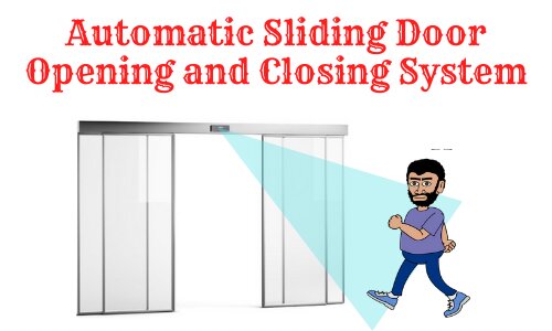
Automatic Sliding Door Opening and Closing System using PIR Sensor and Arduino
Hello friends! Welcome back to ElectroDuino. This blog is based on the Automatic Sliding Door Opening and Closing System using PIR Sensor and Arduino. Here we will discuss Introduction to automatic sliding door system, Project Concept, Block Diagram, Components Required, Circuit/Schematic Diagram, Working Principle, and Arduino code.
Introduction
In this modern-day, everything around us becoming automated which makes our life more easy and more advanced. One of the most common systems is the automatic sliding door opening and closing system. We all must have seen this type of automatic sliding door in hotels, shopping malls, theatres, and other commercial buildings. These are the highly visited places where a person is always required to open and close the door for visitors. To reduce human effort most commercial buildings are used automatic sliding doors. This system is used to open the door when a person comes in front of the entrance of the door and closes it automatically after entering into the door.
In this project tutorial, we will be learned How to make an automatic door opening and closing system using PIR sensors, Arduino, and how its works.
Project Concept of Automatic Sliding Door
This project concept is very simple and easy to construct. The main parts of this project are Arduino, PIR Sensor, motor driver IC, and an old PC DVD writer. Where the Arduino is the main microcontroller that will be used to control the whole system. The PIR sensor is able to sense the infrared energy produced by the human body. For this reason in this project is used to detect human movement. The motor driver IC is used to control the DC motor of the old PC DVD writer. For the demonstration purpose, here we will use an old PC DVD writer to replicate the door.
This system works like that when someone comes in front of the door (PIR Sensor), then the PIR sensor detects a motion and produces high output. Arduino read that output and send commands to the L293D motor driver IC to open the door by controlling the DC motor of the DVD writer.
When nobody is present in front of the door, the PIR sensor doesn’t detect any motion and produces high output. Again the Arduino read this that output and sends commands to the L293D motor driver IC to close the door by controlling the DC motor of the DVD writer.
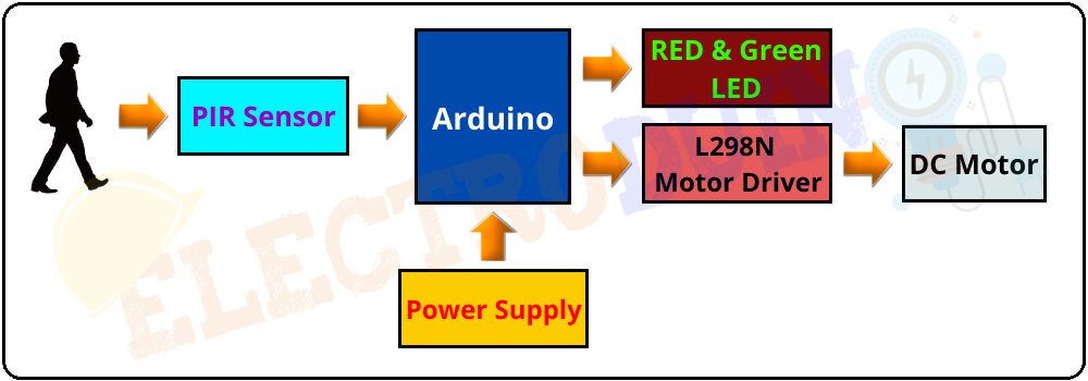
Block Diagram of Automatic Sliding Door Opening and Closing System using PIR Sensor and Arduino
Components Required
| Components Name | Quantity |
| Arduino Nano or Arduino Uno | 1 |
| USB Cable for Arduino | 1 |
| PIR Motion Sensor HC-SR501 | 1 |
| L298N Motor Driver | 1 |
| Old PC DVD writer (DC Motor) | 1 |
| Green LED | 1 |
| Red LED | 1 |
| 220 ohm Resistor | 2 |
| Slide Switch |
1 |
| 9V power supply | 1 |
| PCB board or Breadboard | 1 |
| Connecting wires | As required in the circuit diagram |
Tools Required
| Tools Name | Quantity |
| Soldering Iron | 1 |
| Soldering wire | 1 |
| Soldering flux | 1 |
| Soldering stand | 1 |
| Multimeter | 1 |
| Desoldering pump | 1 |
| Wirecutter | 1 |
Circuit Diagram of Automatic Sliding Door Opening and Closing System using PIR Sensor and Arduino
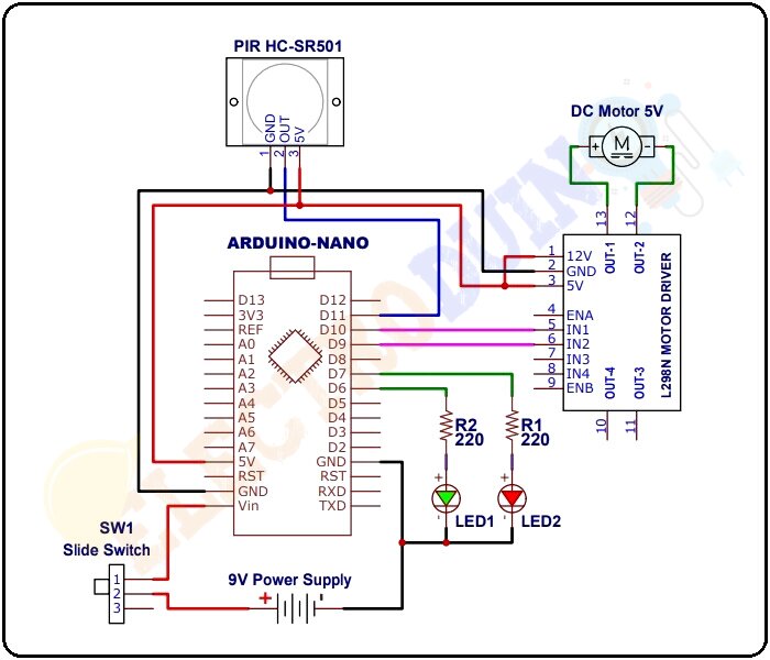
Circuit Design
In this project, we have used Arduino nano as the microcontroller to control the system, you can use any other microcontroller board of Arduino like Arduino Uno, Mega, etc. Circuit diagram and code is same for other Arduino boards.
At first, connect the Data OUT pin of the PIR Sensor to the Digital Pin 11 of Arduino. The +5V (Vcc) and GND pins of the PIR Sensor are connected to +5V and GND of Arduino respectively.
Now coming to the Motor Driver, here we have used the first channel of the L298N Motor Driver Module to control the motor. Hence, the IN1 and IN2 of the Motor Driver are connected to Digital Pins 10 and 9 of Arduino respectively. Here we don’t need to control the speed of the DC motor, so don’t remove the jumper pin of the ENA pin that connects this pin to +5 V. As a result, the motor will rotate at its maximum speed.
In the project, we have used the DVD writer motor that is a 5V Motor. So, we have connected the +5V power supply pin of the Arduino to the both Motor Driver Module and the motor power pin of L298n. The Motor of the DVD writer is connected to the OUT1 and OUT2 of the Motor Driver.
Finally, LED1 and LED2 are connected to Digital Pins 6 and 7 respectively.
Working Principle
Generally, the human body emits infrared energy. When a human body comes in the detection range of the PIR sensor then it detects the infrared energy of the human body and gives High output (+5v) from the output pin. When it doesn’t detect the infrared energy of the human body, then it gives Low output (0) from the output pin. In this way, the PIR sensor detects motion and produces output.
In this automatic sliding door opening and closing system, the PIR sensor is placed at the top of the entrance. When a person comes in the range of PIR Sensor, then the PIR sensor detects the motion of that person and its Data OUT Pin will become HIGH (+5). Then the digital pin 11 (D11) of Arduino read this HIGH output and it understands that there is a person approaching the door. Then the digital pin 10 and pin 9 of Arduino become High (+5) and Low (0) respectively that immediately activates the L298N Motor Driver module to start rotating the DC motor at one direction and the door opens. At the same time, Green LED (LED1) starts glowing that indicating the door is open.
After some time (about 5 seconds in this project), the digital pin 10 and pin 9 of Arduino become Low (0) and High (+5) respectively, which will once again activate the L298N Motor Driver module to start rotating the DC motor in another direction. Now the door will close automatically. This time, Green LED (LED1) becomes turned off and Red LED (LED2) starts glowing, which indicates the door is closed.


